
Liquid container, liquid using device, printing apparatus, and method of manufacturing liquid container

Inactive Publication Date: 2004-10-07
CANON KK
View PDF16 Cites 122 Cited by
  • Summary
  • Abstract
  • Description
  • Claims
  • Application Information

AI Technical Summary

Benefits of technology

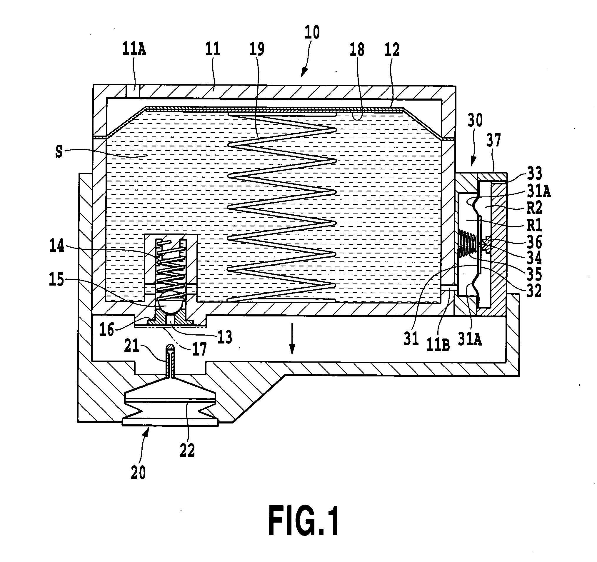
[0027] a one-way valve to allow an introduction of a gas from the outside into the accommodation space and prevent the liquid and gas from flowing out of the accommodation space to the outside;
[0037] In the sixth aspect of the present invention, there is provided a method of manufacturing a liquid container, wherein the liquid container includes: an accommodation portion to define a liquid accommodation space; a liquid supply portion to supply a liquid accommodated in the accommodation space to an outside; a mechanism to maintain or expand a volume of the accommodation space; and a one-way valve to allow an introduction of a gas from the outside into the accommodation space and prevent the liquid and gas from flowing out of the accommodation space to the outside;
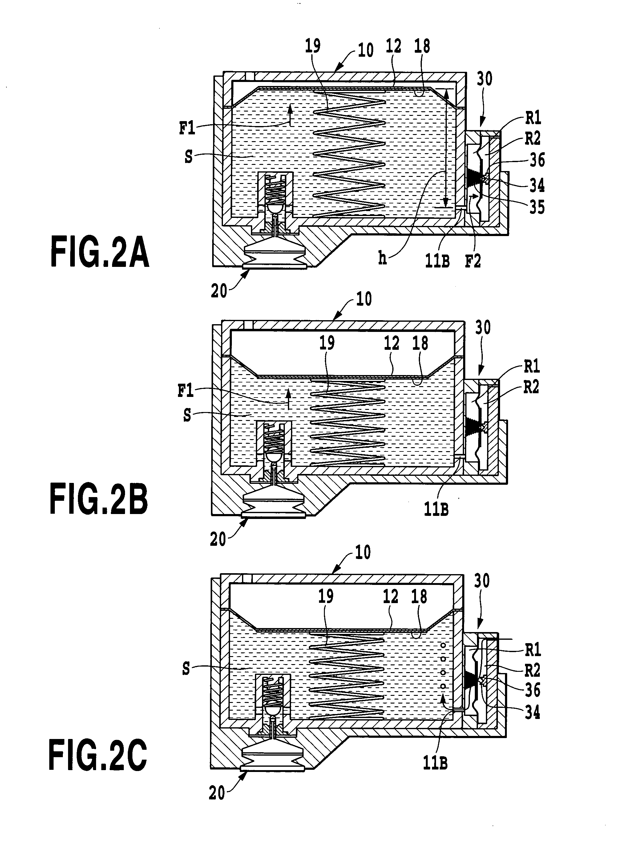
[0042] The inventors of this invention have found that, when introducing air into a liquid container to prevent a negative pressure rise in the container, it is not desirable to totally eliminate the negative pressure in the container but it is important to return the negative pressure to an original, predetermined level. To this end, it is also found that an appropriate volume of air needs to be introduced. Particularly when a liquid container is used as an ink tank for directly supplying ink to an ink jet print head, the supply of ink at a stable flow velocity and in a stable flow volume is essential in enhancing a printing speed and image quality. To realize this, it is strongly desired that a resistance that the ink generates as it flows through an ink supply path be kept almost constant. It is therefore important to stabilize the negative pressure in the ink tank and keep it in a predetermined range. This requires components that introduce air into the ink tank to operate reliably.

Problems solved by technology

With these negative pressure generation mechanisms, however, the negative pressure generated tends to increase as the amount of ink remaining in an ink tank (bag-like member) decreases.
When the negative pressure exceeds a predetermined level, ink can no longer be supplied stably to a print head.
This gives rise to a possibility of the ink tank becoming unfit for use before the ink in the ink tank is completely consumed.
As a result, the negative pressure may increase in excess of an appropriate range that allows normal ink ejections from a print head, making it impossible for an adequate meniscus to be formed at the ink ejection portions of the print head or to supply ink stably to the print head.
In this case, not all of the ink volume in the bag member cannot be used.
This kind of bag member, however, has a limitation on the shape.
Even with this bag member, when the ink is about to be used up, the negative pressure is so high as will cause a performance degradation in supplying ink to the print head or make the ink ejection operation of the print head unstable.
These negative pressure adjust mechanisms disclosed in U.S. Pat. Nos. 5,917,523, 5,600,358 and Japanese Patent Application Laid-open No. 6-183023 (1994), however, all require a plurality of parts in the air take-in portion, rendering the construction that much complicated.
Although the mechanical construction is relatively simple, this adjust mechanism lacks a stability in maintaining the hermetically closed system.
That is, the liquid seal in the orifice may be broken depending on various conditions, resulting in a leakage of accommodated ink.
The humidity variations therefore make an air introducing operation unstable, which in turn may lead to a performance reduction in supplying ink to the print head and to a degraded quality of printed images.
The provision of the inlet maze, however, complicates the construction.
Further, since the other end of the inlet maze (maze-like path) communicates with open air at all times, the ink unavoidably evaporates to some degree through this inlet maze.
There is another problem.
At this time, the inrush air may cause the ink remaining in the print head and the ink tank to leak out of nozzles or through the ring-shaped orifice in which the meniscus has been broken.
When ink in the ink container is almost running out and a volume of air in the ink container is larger than that of ink, if the atmosphere is introduced into the ink tank through the opening, the maintenance of a meniscus in the liquid-sealed opening of the container and in the ink nozzle openings of the print head may become incomplete.
This in turn may cause an ink leakage and render the introduction of air incomplete.
Depending on a variety of conditions the liquid seal in the opening may be broken, resulting in an early introduction of air before the pressure in the ink container reaches a predetermined value or, conversely, a leakage of ink.
These conditions change depending on the design of the print head and ink tank and a physical property of ink, so it is difficult to properly design a shape and dimensions of the opening.
The negative pressure adjust mechanisms using the liquid seal described above may also reduce a degree of freedom of design in the printing apparatus.
That is, it is difficult to form the liquid seal portion separate from the ink tank and then removably mount it on the ink tank.
Refilling the tube with ink after the air introduction requires complicated processing or construction.
As a result, the negative pressure level at which the air introduction is executed may become unstable.
However, low-rigidity materials used for such a flexible sheet generally have a small thickness and a high gas permeability, so air can easily pass through it.
Thus, if ink is stored in the ink bag for a long period of time, a large volume of air, so large as cannot be dealt with by a buffer function originally intended to absorb an expanded portion of gas (air) in the ink bag, enters into the ink bag, rendering the buffer function ineffective.
It is therefore necessary to use a very expensive material deposited with a metal vapor to meet both of the requirements of a low rigidity and a low gas permeability.
Thus, if the member is immersed in ink, component materials of the member may dissolved into the ink, degrading reliability of ink and printed images.
Further, characteristic changes of the member may render a correct pressure adjustment impossible.
This in turn shifts a timing at which the one-way valve 30 is operated, rendering the negative pressure in the accommodation space S unstable.

Method used


Image

  • Liquid container, liquid using device, printing apparatus, and method of manufacturing liquid container
  • Liquid container, liquid using device, printing apparatus, and method of manufacturing liquid container
  • Liquid container, liquid using device, printing apparatus, and method of manufacturing liquid container

Examples


Embodiment Construction

[0111] In the example, a planar flexible sheet 31' is used as the flexible sheet of the one-way valve 30. In a process of assembling the one-way valve, the flexible sheet 31' is raised at its central portion by the valve restraining spring 35 as shown in FIG. 5A and then is pushed down by the valve seal member 36 to form an irregular fold or wrinkle in a undulated portion 31A' as shown in FIG. 5B. That is, after the flexible sheet 31' is given a tension by the valve restraining spring 35, a portion around the opening 34 is pressed down by the valve seal member 36 to close the opening 34. As the opening 34 is closed, an irregular fold is formed in the freely deformable undulated portion 31A'. This undulated portion 31A' assures a freedom of deflection of the flexible sheet 31'.

[0112] However, the undulated portion 31A' in which an irregular fold is formed may cause a sudden sharp change in the amount of deformation as the pressure P in the valve chamber R1 changes. Suppose, for examp...


PUM


Abstract

This invention provides a liquid container capable of stably supplying a liquid contained therein, a liquid using device, a printing apparatus, and a method of manufacturing the liquid container. In one preferred embodiment of this invention, a one-way valve used in an ink tank is constructed of a flexible sheet. In an area of the flexible sheet, an undulated portion is formed whose undulated form is maintained in an operation range of the one-way valve.

Description

[0001] This application claims priority from Japanese Patent Application Nos. 2003-102071 filed Apr. 4, 2003 and 2004-061418 filed Mar. 4, 2004, which are incorporated hereinto by reference.[0002] 1. Field of the Invention[0003] The present invention relates to a liquid container capable of stably supplying a liquid such as ink contained therein, a liquid using device, a printing apparatus, and a method of manufacturing the liquid container.[0004] 2. Description of the Related Art[0005] An ink tank for directly supplying ink to a print head capable of ejecting ink has a negative pressure generation mechanism that generates a negative pressure to be applied to the ink. The negative pressure generated by the negative pressure generation mechanism is set in an appropriate range that is large enough to balance with a retaining force of an ink meniscus formed at ink ejection portions in the print head to prevent leakage of ink from the ink ejection portions and which also allows ink ejec...

Claims


Application Information

Patent Timeline
IPC IPC(8): B41J2/175B65D83/00
CPCB41J2/17513B41J2/1752B41J2/17559B41J2/17596
Inventor OGURA, HIDEKIMATSUMOTO, RYOICHIINOUE, RYOJINANJO, TATSUO
Owner CANON KK
Learn More