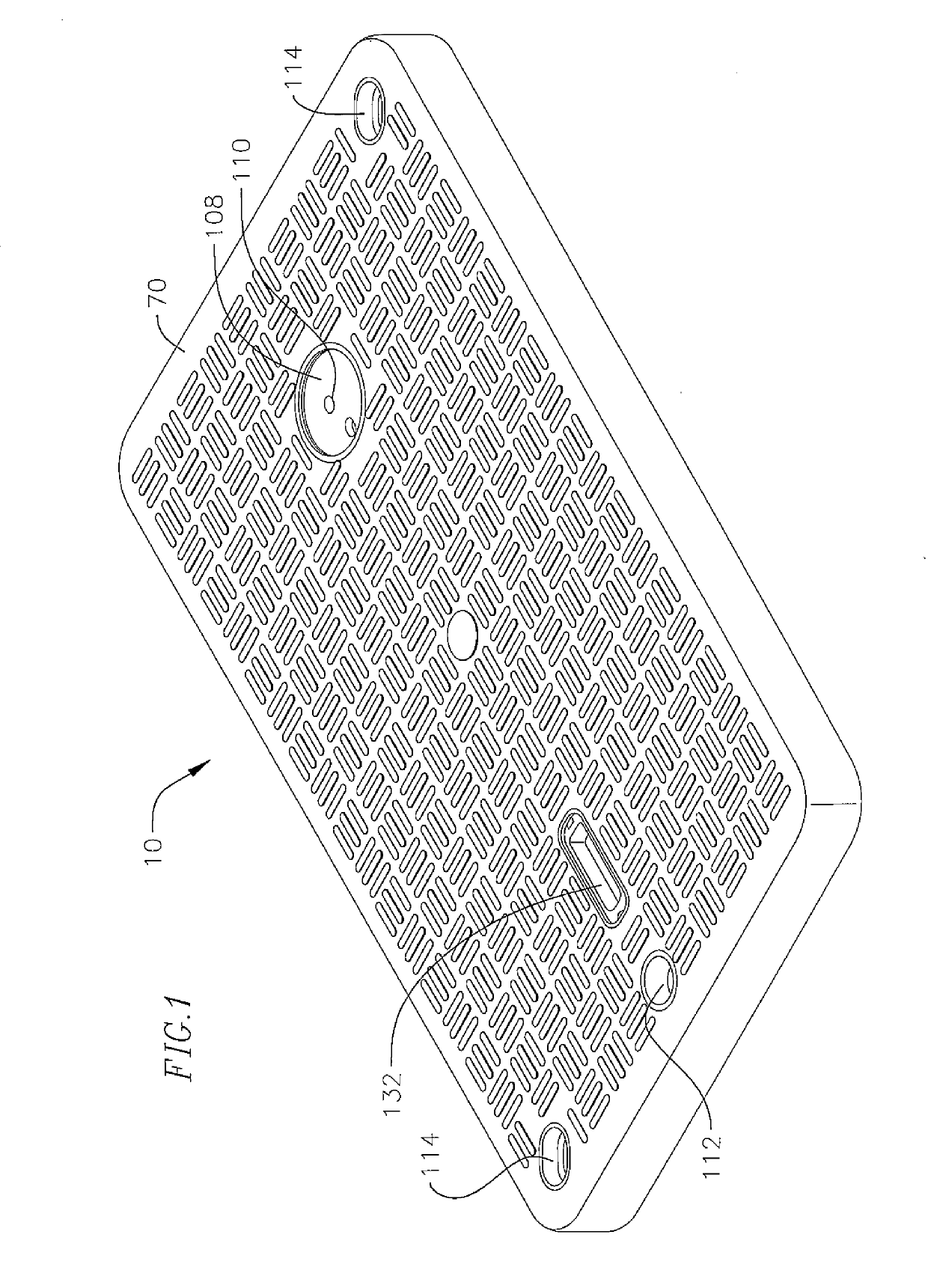
Method of manufacturing a thermoset polymer utility vault lid
a thermoset polymer and utility vault technology, applied in the direction of stoppers, synthetic resin layered products, packaging, etc., can solve the problems of over 100 pounds, injury or other back problems of workers, difficult to remove for repair, maintenance or adding additional services, etc., to improve uv characteristics and slip resistance, reduce weight, and increase strength
- Summary
- Abstract
- Description
- Claims
- Application Information
AI Technical Summary
Benefits of technology
Problems solved by technology
Method used
Image

Examples
example manufacturing
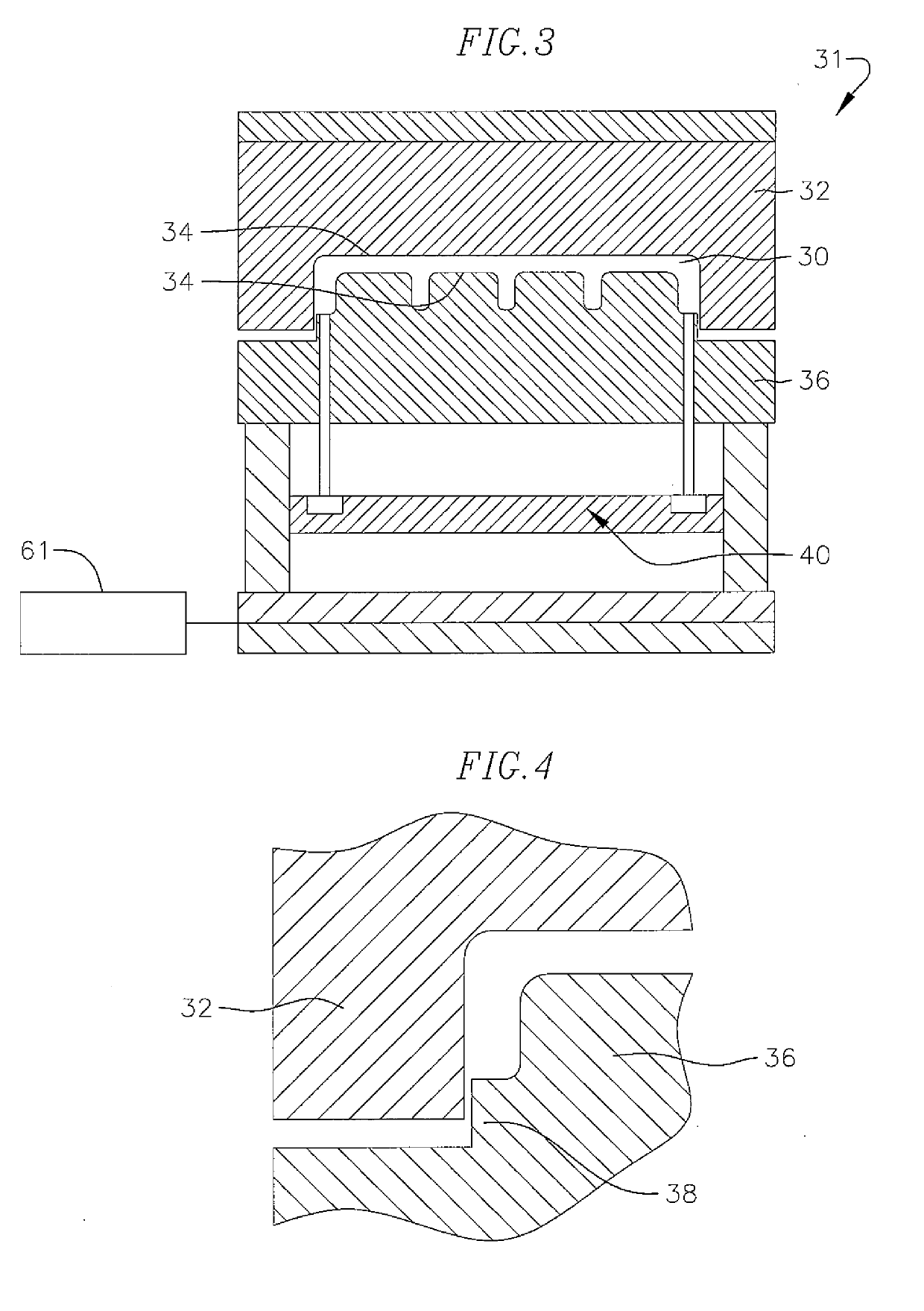
Process for an Embodiment of the Invention
[0040]
Mixing and StoringPolymer FormulationIngredientsDesired %RangePolyester Resin23.2510-40%Polystyrene (Shrink Control)11.46 5-30%Catalyst0.390.1-8% Inhibitor (PBQ)0.260.1-8% Fiber Wetting Additive0.350.1-8% Zinc Stearate (Mold Release)1.210.1-8% Inorganic Filler24.9915-50%Magnesium Oxide (Thickener)1.210.1-8% UV Stable Pigment (Gray)1.890.1-10% Fiberglass (0.5″-2″ Chopped)35.0 5-60%
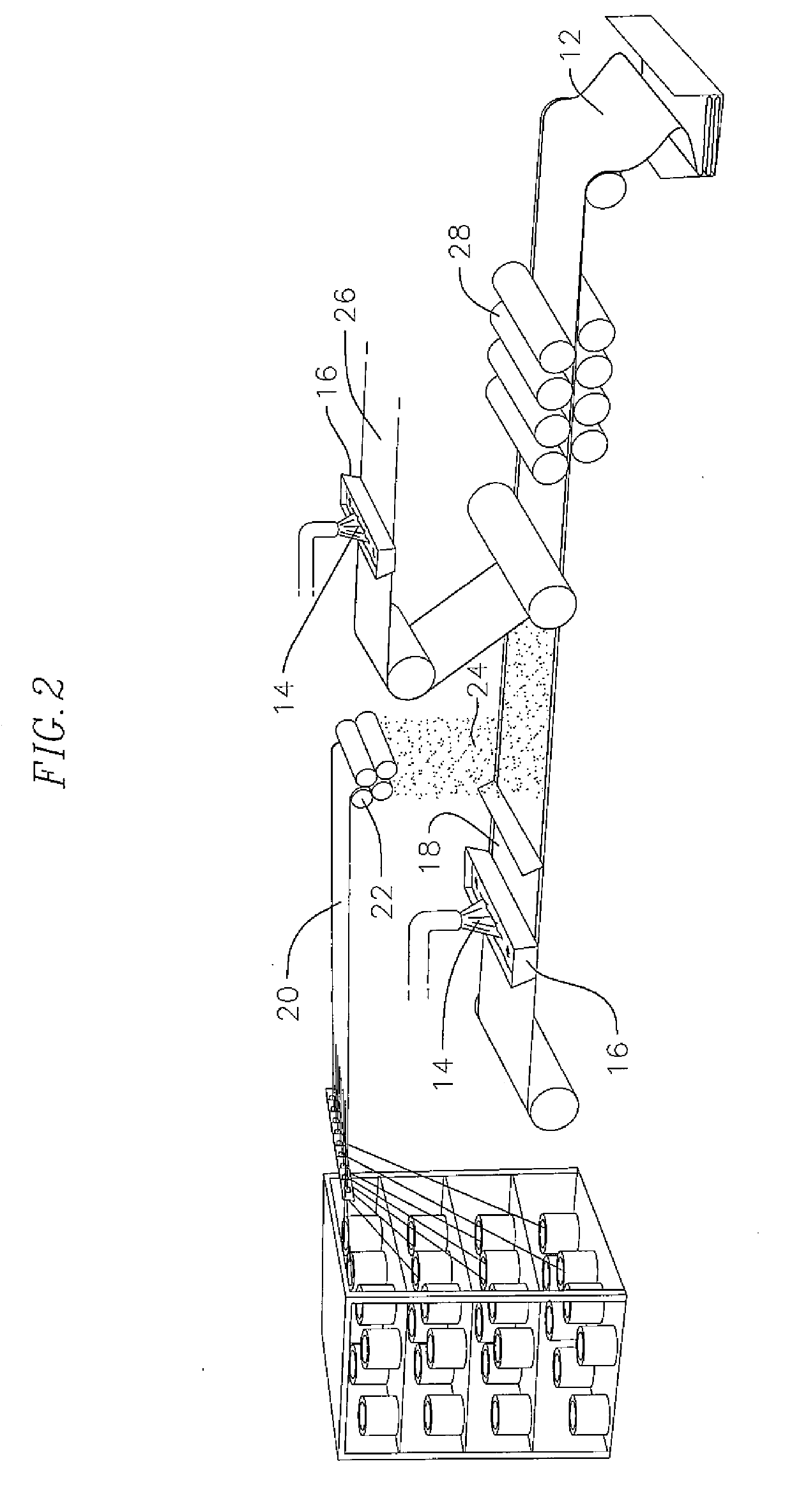
[0041]The polymer formulation is typed into an automated delivery system. This system is responsible for mixing of all of the ingredients together, storing the polymer matrix and then delivering it to a compounder, for example a Schmidt and Heinzmann (S&H) Compounder.
[0042]The formulation is mixed to ensure that the material is homogeneous. Controllers manipulate the order of addition, dwell time, blade speed and mixing temperature. Upon completion of paste matrix mixing cycle, several tests are performed to make certain the paste is correct before being ...
PUM
| Property | Measurement | Unit |
|---|---|---|
| lengths | aaaaa | aaaaa |
| formulation | aaaaa | aaaaa |
| Molding Pressure | aaaaa | aaaaa |
Abstract
Description
Claims
Application Information
 - R&D
- Intellectual Property
- Life Sciences
- Materials
- Tech Scout
- Unparalleled Data Quality
- Higher Quality Content
- 60% Fewer Hallucinations
Browse by: Latest US Patents, China's latest patents, Technical Efficacy Thesaurus, Application Domain, Technology Topic, Popular Technical Reports.
© 2025 PatSnap. All rights reserved.Legal|Privacy policy|Modern Slavery Act Transparency Statement|Sitemap|About US| Contact US: help@patsnap.com