Hybrid 3D optical scanning system

a hybrid measurement system and optical scanning technology, applied in the field of metalrology systems, can solve the problems of reducing the accuracy of the measurement, so as to achieve accurate and reliable measurement results

Active Publication Date: 2019-06-06
VEHICLE SERVICE GROUP LLC
View PDF0 Cites 4 Cited by
  • Summary
  • Abstract
  • Description
  • Claims
  • Application Information

AI Technical Summary

Benefits of technology

[0007]Accordingly, it is a general purpose and object of the present invention to provide an improved optical scanning system for providing 3D surface measurements of objects of varying size and dimension that are more accurate and reliable in their measure than heretofore provided by the prior art systems.

Problems solved by technology

Measuring dents, deformations and other defects of articles under inspection, especially those of specular, glossy metallic surfaces of automotive, aerospace and other manufactured parts presents a problem due to reflective nature of those surfaces.
Typical metrology systems in this field of article inspection rely on measuring contrast of projected patterns on those surfaces, but since most of these surfaces have both high curvature and high reflectivity, most of projected light is reflected away from camera, and produce very low contrast images of projected patterns.
It is even more problematic when those above-described object surfaces are of dark colors and / or metallic paint type, where tiny metallic particles are suspended in a translucent coating.
Detection and resolution of all these differing reflections can be very complicated and prove to be compromising to the precision of the metrology system to the point where measurement errors becomes larger than the desired accuracy of measurement, especially in the areas of small defects, dents and scratches thereby making detection and reliable measurement of above mentioned articles either unreliable or impossible.
All of these systems are suffering from above mentioned reflectivity issues and produce low contrast images and noisy measurement results.
Laser based system suffers from disadvantage of requiring moving parts and long acquisition times to measure large parts or surfaces.
Stereo vision based systems are especially sensitive to reflectivity variations and produce least reliable results.
Multiple pattern digital projection active stereo 3D reconstruction systems produce better results, but still have large measurement errors in areas of above mentioned defects and therefore do not produce reliable enough results.
These requirements can pose serious limitations as the size of screens are limited and subject to tolerances on flatness and the spatial configuration of the deflectometry system often fails to be reasonable to measure large areas.
Although deflectometry is capable of detecting local changes in curvature (such as dents and deformations) very well, due to ambiguities in the principle it is not capable of deriving absolute shape of the object with high accuracy, as this shape is extracted by assuming one can integrate the curvature information.
While these separate system methodologies have been generally satisfactory, subject to their respective limitations, in collecting measurable data through optical scanning and detection from the surfaces of relatively smaller objects, those limitations described above have been found to be unreliable in obtaining highly accurate measurement data from larger object surfaces needed to produce high resolution images of the object surfaces.

Method used


Image

  • Hybrid 3D optical scanning system
  • Hybrid 3D optical scanning system
  • Hybrid 3D optical scanning system

Examples


Embodiment Construction

[0033]The following serves to describe a preferred embodiment and alternative variations of the present invention and the best presently contemplated mode of its production and practice. This description is further made for the purpose of illustrating the general principles of the invention but should not be taken in a limiting sense, the scope of the invention being best determined by reference to any associated claims.

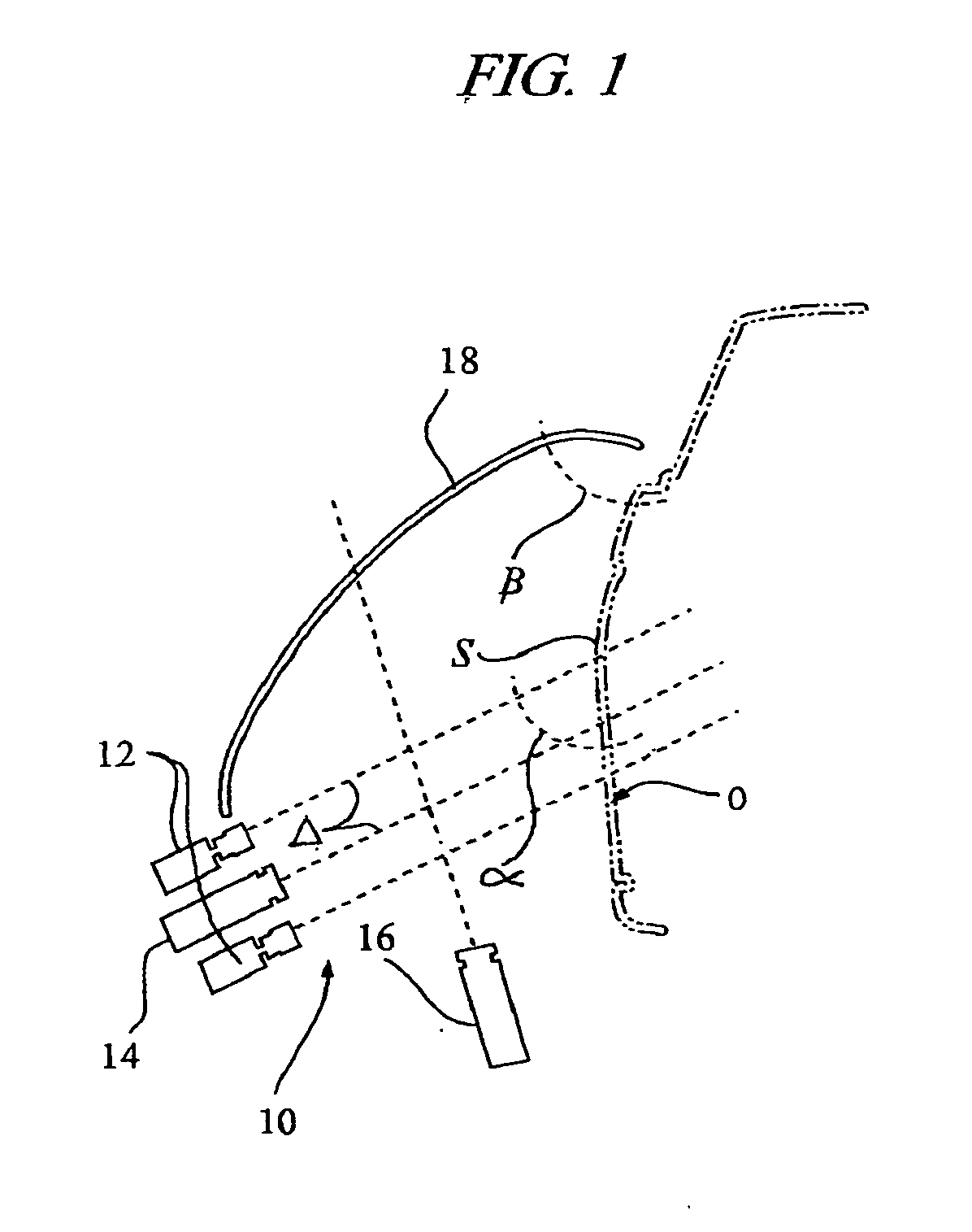
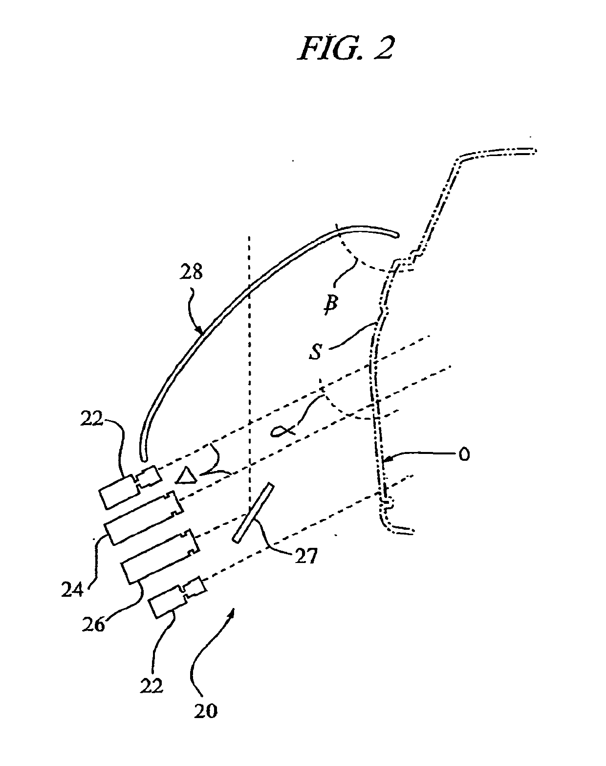
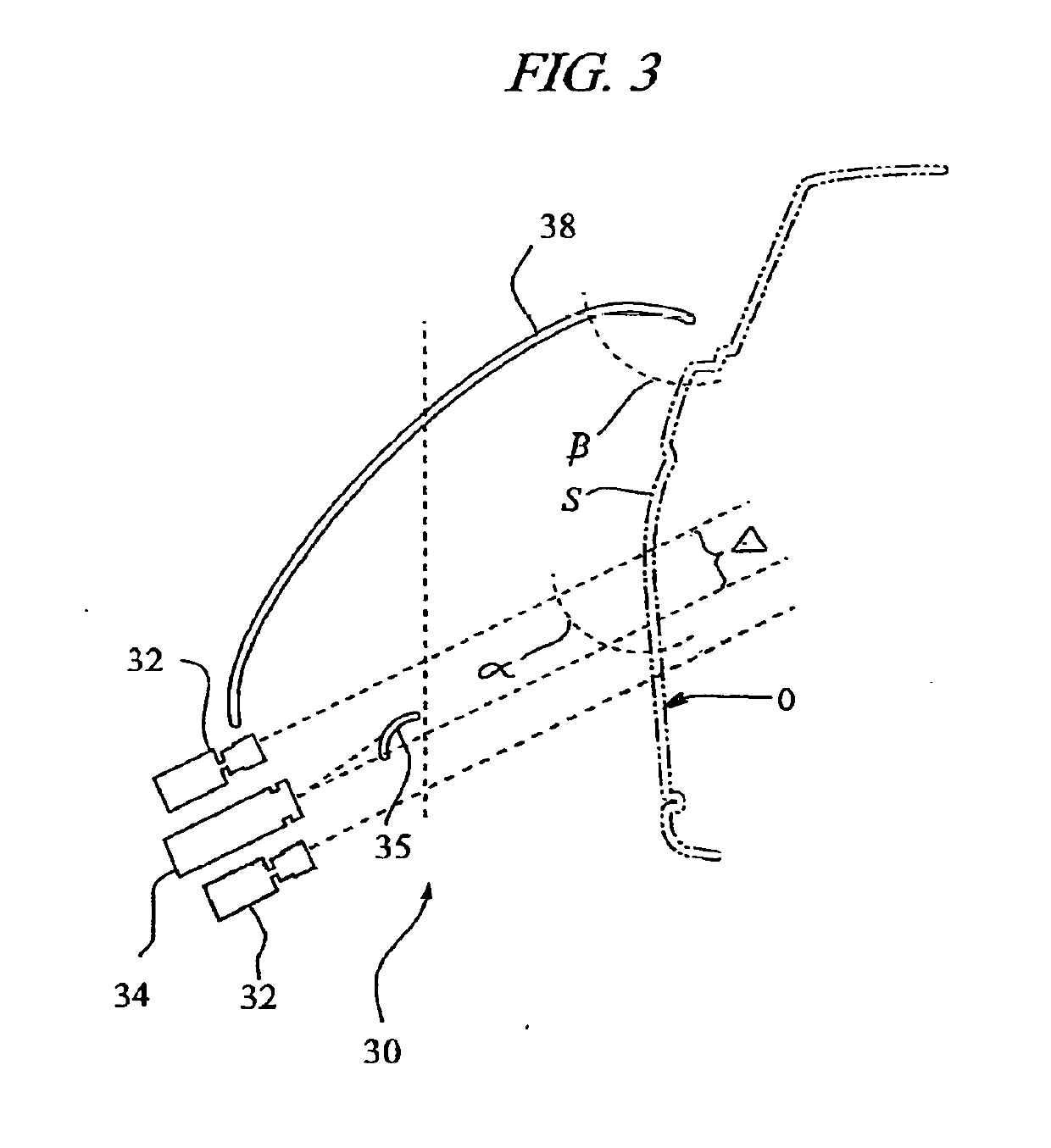
[0034]Referring to the drawings, the following is a list of component elements of the present hybrid active stereo 3D construction-deflectometry system, generally designated 10 in FIG. 1 and in further variations as 20, 30, 40, 50 and 60 in FIGS. 2, 3, 4, 5 and 6, respectively, and those associated components employed in connection with the present invention:[0035]10 hybrid active stereo 3D construction-deflectometry system;[0036]12 digital camera stereo pair;[0037]14 first digital projector (for active stereo 3D reconstruction);[0038]16 second digital projector (for...


PUM


Abstract

A hybrid 3D optical scanning system combining methodologies of active stereo 3D reconstruction and deflectometry to provide accurate 3D surface measurements of an object under inspection. In a preferred embodiment, the present system comprises a calibrated digital camera stereo pair and first digital projector for active stereo 3D reconstruction metrology positioned at selected distance apart on the same horizontal plane facing the inspection object at an optimal incidence angle relative to the object surface. A secondary digital projector for deflectometry is directed to project a pattern sequence across the optical projection path of the first digital projector and onto a nonplanar deflection screen extended between the digital camera and the inspection object at a selected angle relative thereto, the selected angle being chosen so that that the pattern projected onto the deflection screen by the secondary digital projector reflects from the surface of the inspection object towards the digital camera. Calibrated active stereo 3D reconstruction is used to derive global shape and the uncalibrated nonplanar deflected light acquires curvature of local fine deformations and surface imperfections along the object surface. The calibrated camera allows per pixel correlations to be defined between the separate acquisition methods and produces accurate absolute measurements of both shape and local features of specular, glossy, metallic curved surfaces.

Description

BACKGROUND OF THE INVENTION[0001]The present invention relates to metrology systems used to provide precise measurements of three-dimensional (3D) surfaces of articles under inspection and more particularly, to an improved hybrid measurement system using calibrated active stereo 3D reconstruction and uncalibrated nonplanar deflected or back-projection reflectometry to acquire and accurately measure both global shape and local fine deformations, dents and surface imperfections of specular, glossy and metallic surfaces of industrial, automotive and aerospace components and parts.[0002]Measuring dents, deformations and other defects of articles under inspection, especially those of specular, glossy metallic surfaces of automotive, aerospace and other manufactured parts presents a problem due to reflective nature of those surfaces. Typical metrology systems in this field of article inspection rely on measuring contrast of projected patterns on those surfaces, but since most of these sur...

Claims


Application Information

Patent Timeline
Patent Type & Authority Applications(United States)
IPC IPC(8): G01B11/25
CPCG01B11/2513G01B11/2518
Inventor GRAUZINIS, AIVARAS ALFONSASWILLEMS, GEERT
Owner VEHICLE SERVICE GROUP LLC
Why Eureka
Try Eureka