
Method and apparatus for wire rope distance measurement

a distance measurement and wire rope technology, applied in the field of non-destructive evaluation of wire ropes and cables, can solve the problems that manufactures may not accede to attaching markers, and achieve the effect of accurate correlation, extremely accurate and reliabl

Active Publication Date: 2015-07-16
NDT TECH LLC
View PDF1 Cites 9 Cited by
  • Summary
  • Abstract
  • Description
  • Claims
  • Application Information

AI Technical Summary

Benefits of technology

The patent text describes methods and apparatus for accurately measuring the distance along a wire rope, which is important for determining its condition and making safe and economical retirement decisions. The technical effects of the invention include the ability to attach markers along the length of the rope and the use of magnetic or optical sensors to detect these markers and establish calibration parameters for accurate distance measurements. The invention also provides apparatus for measuring distance along a measurement path using magnetic homogenizers and magnetizing coils. Overall, the invention allows for more precise and reliable examination of wire rope condition and facilitates its safe and economical use.

Problems solved by technology

However, manufacturers may not accede to attaching markers during production of wire ropes.

Method used


Image

  • Method and apparatus for wire rope distance measurement
  • Method and apparatus for wire rope distance measurement
  • Method and apparatus for wire rope distance measurement

Examples


Embodiment Construction

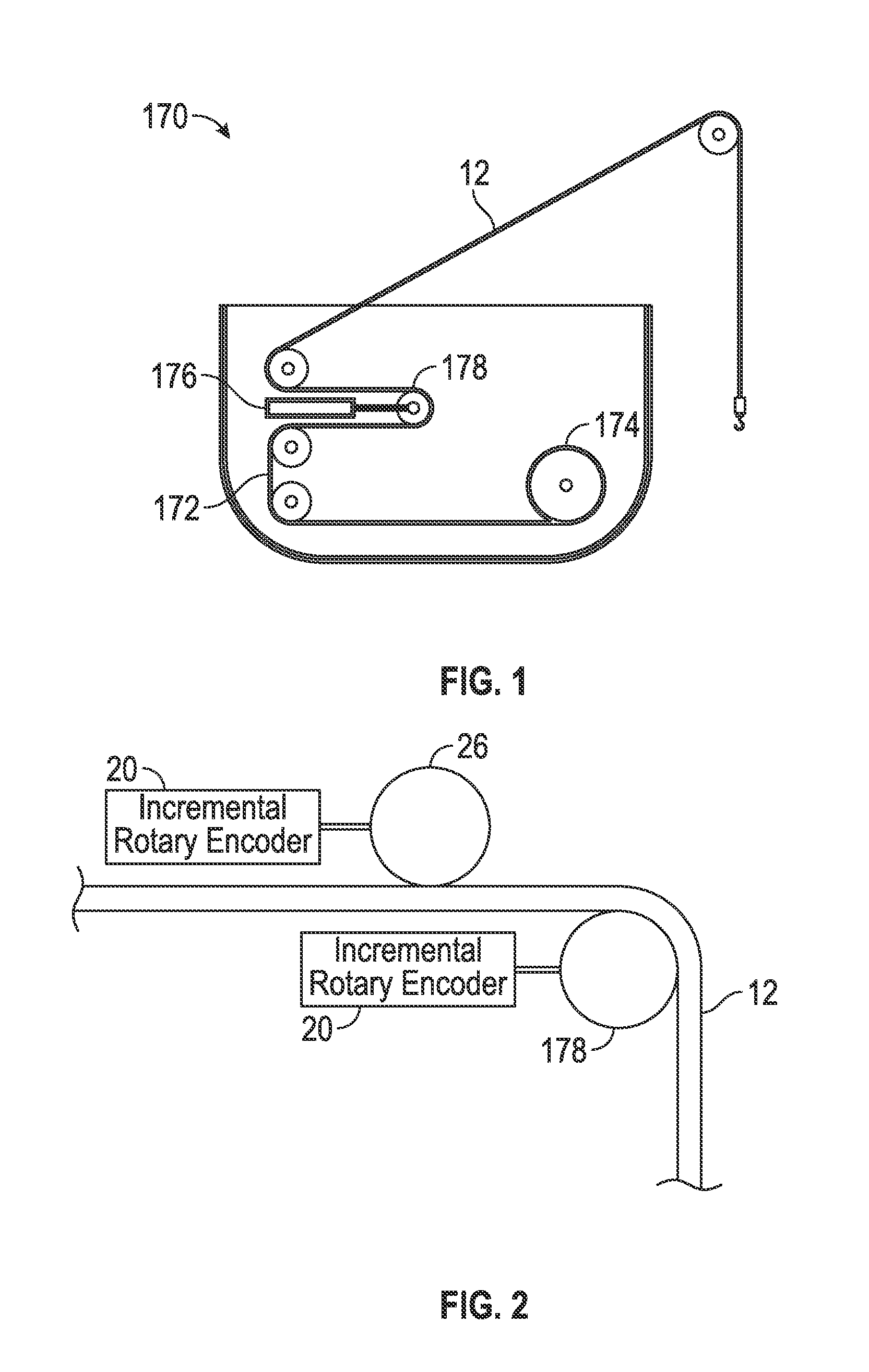
[0035]Although embodiments of the invention are shown in the drawings and are described as relating to distance measurements along high-value wire ropes, aspects of the invention more generally may be applicable to distance measurements along any sort of cable.

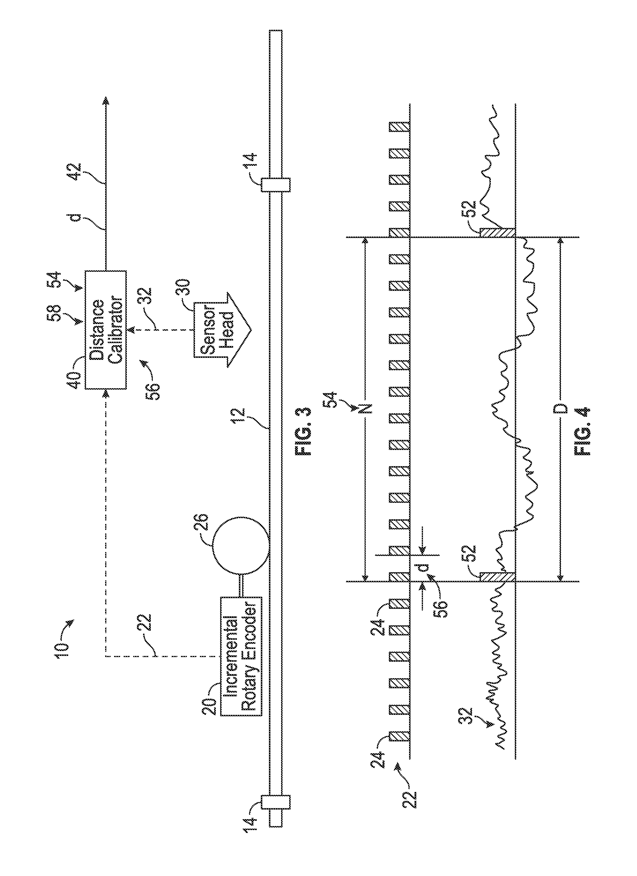
[0036]FIG. 3 shows a functional block diagram of a distance calibration apparatus 10, according to a first embodiment of the invention. The inventive apparatus 10 is configured for use with a wire rope 12. According to a typical embodiment, the wire rope 12 carries at least two distance markers 14, which are spaced apart at a well defined known distance, D. The distance markers 14 can be permanently attached to the wire rope 12, however, permanent attachment is not essential to the invention. The wire rope 12 is positioned adjacent an Incremental Rotary Encoder 20 and a sensor head 30, which are components of the apparatus 10 that define a measurement path for the wire rope 12. The incremental rotary encoder 20 produces an Inc...


PUM


Abstract

Measuring distance along a wire rope, by steps that include moving the wire rope across a sensor head; counting rotations of a rotary encoder driven by the moving wire rope; detecting a first distance marker crossing the sensor head at a first position of the wire rope; detecting a second distance marker crossing the sensor head at a second position of the wire rope; and establishing calibration parameters for producing a calibrated distance measurement corresponding to any output of the rotary encoder, based at least on correlating a known distance between the first and second distance markers to a counted number of pulses of the rotary encoder between the first and second positions of the wire rope.

Description

CROSS REFERENCE TO RELATED APPLICATION[0001]This application is a non-provisional of U.S. patent application Ser. No. 61 / 925,866, “Distance Measurement for Wire Ropes,” filed Jan. 10, 2014, hereby incorporated by reference in its entirety.BACKGROUND[0002]1. Technical Field[0003]Embodiments of the invention relate generally to non-destructive evaluation (NDE) of wire ropes and cables during operation under load. Particular embodiments relate to measurements of distance along a loaded wire rope for purposes of NDE.[0004]2. Discussion of Art[0005]Many wire ropes for offshore applications, such as subsea construction ropes and mooring ropes, have large diameters (>100 mm) and lengths in excess of 2000 m. These ropes are expensive and frequently represent multimillion dollar investments, thus, they often are known as high value offshore ropes. For example, large mooring-lines for a wide variety of offshore structures can be classified as high value offshore ropes.[0006]Other high valu...

Claims


Application Information

Patent Timeline
Patent Type & Authority Applications(United States)
IPC IPC(8): G01D5/12
CPCG01D5/12D07B1/145D07B1/148G01B7/026G01B21/042G01D5/2451G01D18/001
Inventor WEISCHEDEL, HERBERT R.
Owner NDT TECH LLC
Learn More