Device and Computer Realizing Calculation of Reservoir Layer of Reservoir Computing
- Summary
- Abstract
- Description
- Claims
- Application Information
AI Technical Summary
Benefits of technology
Problems solved by technology
Method used
Image

Examples
example 1
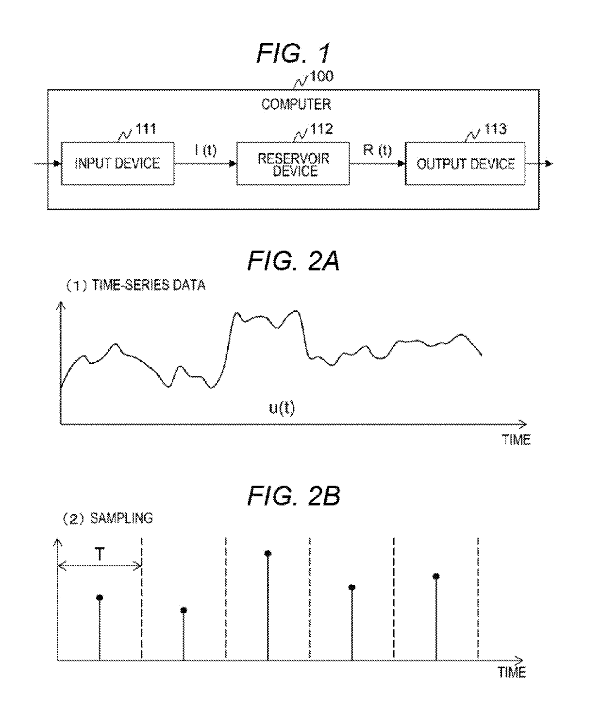
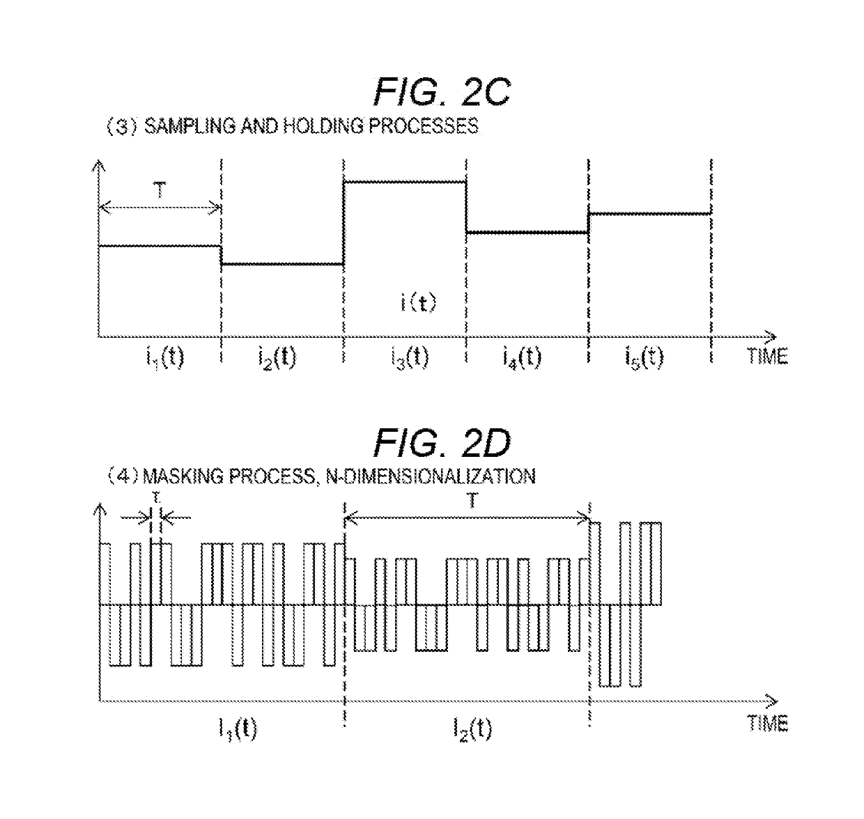
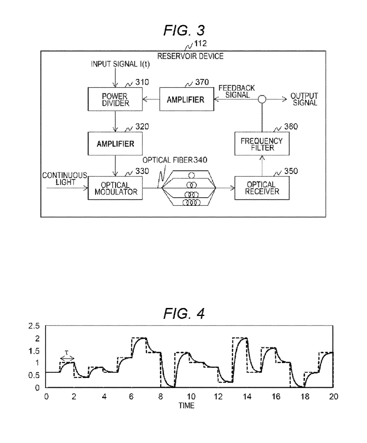
[0042]FIG. 1 is a diagram illustrating a configuration example of a computer realizing reservoir computing according to Example 1. FIGS. 2A to 2D are diagrams illustrating examples of processes executed by an input device according to Example 1. FIG. 3 is a diagram illustrating a configuration example of a reservoir device according to Example 1. FIG. 4 is a diagram illustrating an example of a signal input to a frequency filter 360 according to Example 1.
[0043]A computer 100 that realizes reservoir computing includes an input device 111, a reservoir device 112, and an output device 113.
[0044]The input device 111 is a device that realizes an input unit 1110 of the reservoir computing. Here, a process executed by the input device 111 will be descried with reference to FIGS. 2A to 2D.
[0045]When an input of time-series data u(t) illustrated in FIG. 2A is received, the input device 111 executes sampling and holding processes of sampling the time-series data u(t) and holding values sampl...
example 2
[0092]Example 2 is different from Example 1 in a method of realizing a conversion mechanism. Hereinafter, difference between Example 1 and Example 2 will be mainly described.
[0093]The computer 100 according to Example 2 has the same configuration as that according to Example 1. The input device 111 and the output device 113 according to Example 2 have the same configurations as those according to Example 1. In Example 2, the configuration of the reservoir device 112 is different from that of the reservoir device 112 of Example 1.
[0094]FIG. 9 is a diagram illustrating a configuration example of a reservoir device 112 according to Example 2.
[0095]The configuration of the reservoir device 112 other than an optical fiber 900 according to Example 2 is the same as that of the reservoir device 112 according to Example 1.
[0096]The optical fiber 900 according to Example 2 includes a conversion mechanism that divides and outputs an optical signal output from the optical modulator 330 accordin...
example 3
[0100]In Example 3, a process of the output device 113 is different. Hereinafter, differences between Example 1 and Example 3 will be mainly described.
[0101]The computer 100 according to Example 3 has the same configuration as that according to Example 1. The input device 111 and the reservoir device 112 according to Example 3 have the same configurations as those according to Example 1. In Example 3, a process executed by the output device 113 is different.
[0102]FIG. 10 is a diagram illustrating a concept of signal processing executed by the computer 100 according to Example 3. FIG. 14 is a diagram illustrating a concept of signal processing executed by a computer according to the related art.
[0103]The input device, the reservoir device 1200, and the output device according to the related art execute a process in synchronization with a period T. Accordingly, as illustrated in FIG. 14, an output signal R(T) calculated from the output device I(T) is read to calculate an output value....
PUM
 Abstract
Description
Claims
Application Information
 - R&D
- Intellectual Property
- Life Sciences
- Materials
- Tech Scout
- Unparalleled Data Quality
- Higher Quality Content
- 60% Fewer Hallucinations
Browse by: Latest US Patents, China's latest patents, Technical Efficacy Thesaurus, Application Domain, Technology Topic, Popular Technical Reports.
© 2025 PatSnap. All rights reserved.Legal|Privacy policy|Modern Slavery Act Transparency Statement|Sitemap|About US| Contact US: help@patsnap.com