
Adjustable vehicle seat

a vehicle seat and adjustable technology, applied in the direction of movable seats, roofs, transportation and packaging, etc., can solve the problems of disadvantageous structural design of known vehicle seats, and achieve the effect of simplifying kinematics and reducing the diversity of parts in the vehicle sea

Active Publication Date: 2010-04-29
DR ING H C F PORSCHE AG
View PDF9 Cites 17 Cited by
  • Summary
  • Abstract
  • Description
  • Claims
  • Application Information

AI Technical Summary

Benefits of technology

The invention is a vehicle seat with an inclinable seat part and an inclinable backrest that can be adjusted independently. The seat part is mounted pivotably in bearings at the front and rear, and the backrest is mounted pivotably in the seat part. The seat part and backrest can be adjusted to change the angle of inclination. The invention eliminates the need for separate bearing elements for adjusting the backrest, saving on costs and simplifying the seat's construction. The seat part and backrest are held in a single unit, reducing parts and simplifying assembly. The inclination of the seat part can be adjusted using an electric adjusting means. The invention allows for maximum comfort by enabling the user to adjust the inclination of the backrest.

Problems solved by technology

The known vehicle seat disadvantageously has a structurally highly complicated design with the diverse links for adjusting the inclination of the seat supports and of the posterior and thigh rest.
Furthermore, an adjustment of the inclination of the seat supports causes a corresponding adjustment of the inclination of the backrest, but no compensation for the adjustment of the backrest to the effect that the backrest has an unchanged inclination with respect to the floor of the vehicle so that the vehicle seat user can substantially retain the leaning inclination of his back when the position of the posterior and thigh rest changes.

Method used


Image

  • Adjustable vehicle seat
  • Adjustable vehicle seat

Examples


Embodiment Construction

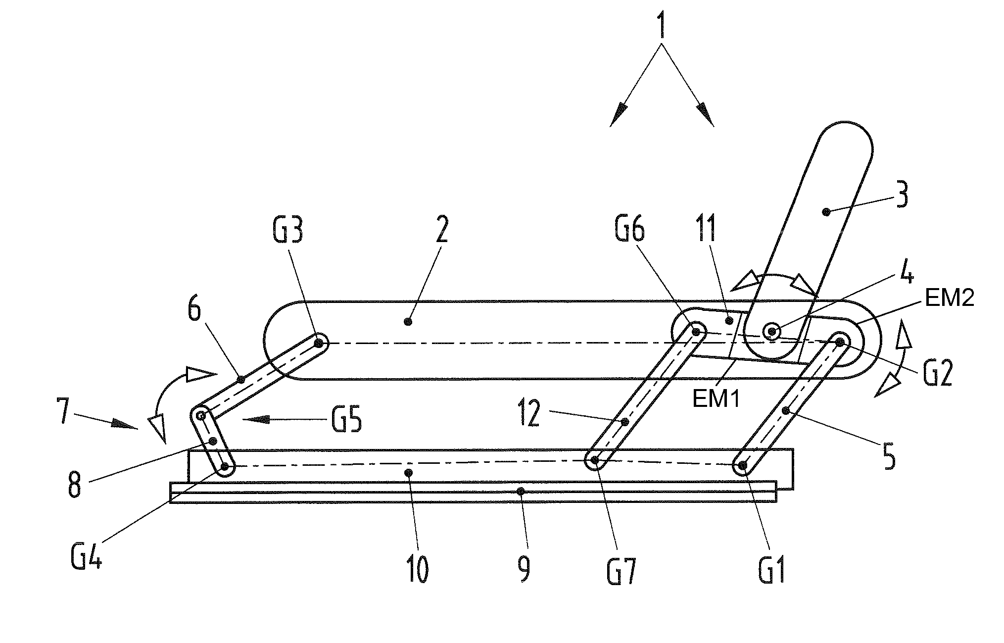
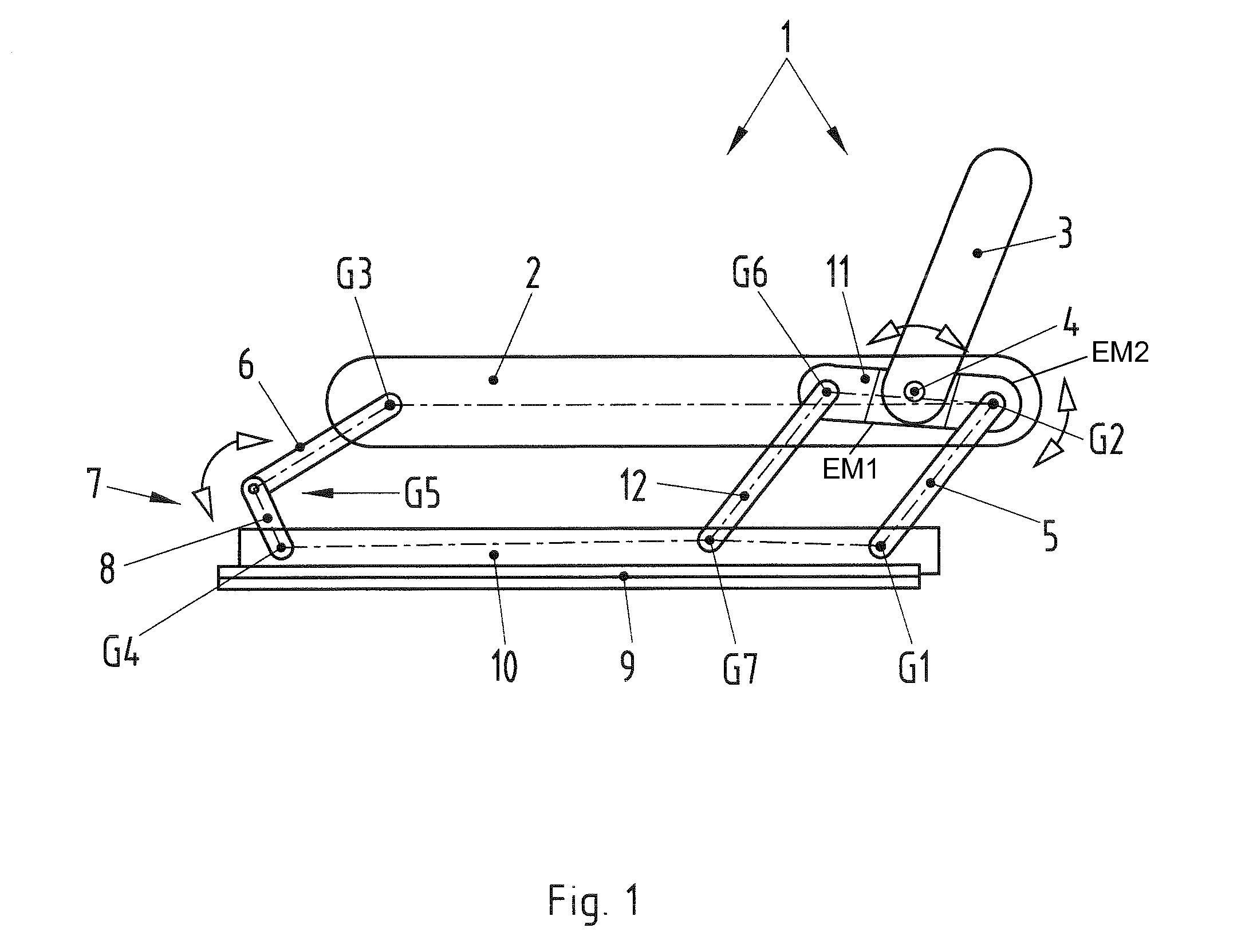
[0027]An adjustable vehicle seat in accordance with the invention is identified generally by the numeral 1 in FIG. 1. The adjustable vehicle seat 1 has a substantially horizontally arranged seat cushion 2 and backrest 3, which is reduced in size and therefore is not illustrated to scale. The seat cushion 2 includes a seat support, a cushion shell mounted in the seat support and a posterior and thigh rest held by the cushion shell. These components of the seat cushion 2 are not shown in FIG. 1. The backrest 3 is connected pivotably about an axis 4 that is arranged transversely with respect to the longitudinal extent of the vehicle. All of the pivot axes described herein are substantially parallel to the axis 4.

[0028]Left and right links 5 are mounted respectively in the left and right sides of the seat cushion 2 at positions behind the axis 4 so that each link 5 can pivot about the axis G2. Additionally, left and right rockers 6 of left and right toggle levers 7 are mounted in the se...


PUM


Abstract

An adjustable vehicle seat (1) has an inclinable seat part (2). Front and rear bearings (7, 5) have upper ends pivotably connected to front and rear areas of the seat part (2) and having lower ends mounted pivotably in bearings (7, 5) in floor rails (10). The front bearings (7) have an adjustable length for changing an inclination of the seat part (2). First additional links (11) are mounted pivotably about a first axis (G2) in the seat part (2). Second additional links (12) have lower ends mounted pivotably in the rails (10) and upper parts connected pivotably to the first additional link (11) at a second axis (G6) spaced from the first axis (G2). An inclinable backrest (3) is mounted pivotably in the first additional link (11).

Description

CROSS-REFERENCE TO RELATED APPLICATIONS[0001]This application claims priority under 35 USC 119 to German Patent Application No. 10 2008 053 476.5 filed on Oct. 28, 2008, the entire disclosure of which is incorporated herein by reference.BACKGROUND OF THE INVENTION[0002]1. Field of the Invention[0003]The invention relates to an adjustable vehicle seat.[0004]2. Description of the Related Art[0005]An adjustable vehicle seat, in particular a motor vehicle seat, has an inclinable seat part and an inclinable backrest mounted to the seat part. The seat part is mounted pivotably in bearings at the front and rear adjacent to remote sides of the seat part. The bearings are mounted pivotably in the vehicle floor or rails for longitudinally adjusting the vehicle seat. The front or rear bearings can be adjusted by adjusting means so that the spacing of the pivot axes of the respective bearing and the inclination of the seat part change.[0006]Vehicle seats, such as those of passenger vehicles, ha...

Claims


Application Information

Patent Timeline
Patent Type & Authority Applications(United States)
IPC IPC(8): B60N2/02
CPCB60N2/0232B60N2/045B60N2/161B60N2/2209B60N2/181B60N2/1814B60N2/1615B60N2/02246
Inventor JUNGERT, DIETERGILBERT, TASSILOHEGER, THOMAS
Owner DR ING H C F PORSCHE AG
Learn More