A wire-actuated joint that enables decoupling of bending motion

A bending motion and joint technology, applied in the field of robotics, can solve problems such as increasing control difficulty

Active Publication Date: 2021-12-17
CHANGSHA UNIVERSITY OF SCIENCE AND TECHNOLOGY
View PDF0 Cites 0 Cited by
  • Summary
  • Abstract
  • Description
  • Claims
  • Application Information

AI Technical Summary

Problems solved by technology

[0005] In order to solve the problem that the wires on the two degrees of freedom will be coupled to each other during the driving process of the joints of the wire-driven robot, which increases the difficulty of control, the present invention provides a wire-driven joint that can realize decoupling of bending motion

Method used


Image

  • A wire-actuated joint that enables decoupling of bending motion
  • A wire-actuated joint that enables decoupling of bending motion
  • A wire-actuated joint that enables decoupling of bending motion

Examples


Embodiment 1

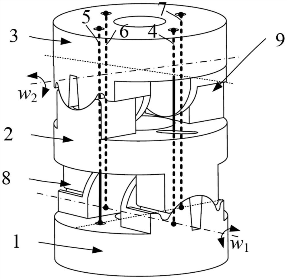
[0033] like figure 1 As shown, this embodiment provides a wire-driven joint capable of decoupling bending motion, including a base plate 1, a connecting rod 2, an end plate 3, a first wire and a second wire; the base plate 1 and The connecting rod 2 is connected to form a first rotating pair 8, and the rotation axis of the first rotating pair 8 coincides with the end surface of the base plate 1; the end plate 3 is connected to the connecting rod 2 to form a second Two rotating pairs 9, the rotation axis of the second rotating pair 9 coincides with the end surface of the end disk 3; one end of the first wire is fixedly connected to the end disk 3, and the other end passes through the end disk 3, The connecting rod 2, the first rotating pair 8 and the base plate 1; one end of the second wire is fixedly connected to the end plate 3, and the other end passes through the end plate 3, the second rotating pair 9, the connecting rod 2 and the Base plate 1.

[0034]In this embodiment...

Embodiment 2

[0042] like figure 1 As shown, this embodiment provides a wire-driven joint capable of decoupling bending motion, including a base plate 1, a connecting rod 2, an end plate 3, a first wire and a second wire; the base plate 1 and The connecting rod 2 is connected to form a first rotating pair 8, and the rotation axis of the first rotating pair 8 coincides with the end surface of the base plate 1; the end plate 3 is connected to the connecting rod 2 to form a second Two rotating pairs 9, the rotation axis of the second rotating pair 9 coincides with the end surface of the end disk 3; one end of the first wire is fixedly connected to the end disk 3, and the other end passes through the end disk 3, The connecting rod 2, the first rotating pair 8 and the base plate 1; one end of the second wire is fixedly connected to the end plate 3, and the other end passes through the end plate 3, the second rotating pair 9, the connecting rod 2 and the Base plate 1.

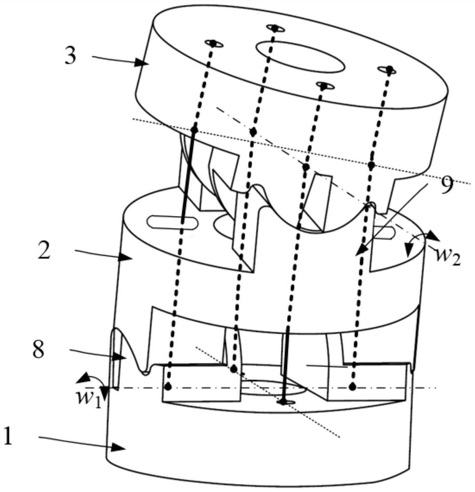
[0043] like Figure 3-5...


PUM


Abstract

The invention discloses a wire-driven joint capable of decoupling bending motion, comprising a base plate, a connecting rod, an end plate, a first wire and a second wire; the base plate is connected with the connecting rod to form a second A rotary pair, the rotation axis of the first rotary pair coincides with the end face of the base plate; the end plate is connected with the connecting rod to form a second rotary pair, the rotation axis of the second rotary pair coincides with The end faces of the end disks are coincident; one end of the first wire is fixedly connected to the end disk, and the other end passes through the end disk, the connecting rod, the first rotating pair and the base disk in turn; one end of the second wire It is fixedly connected with the end plate, and the other end passes through the end plate, the second rotating pair, the connecting rod and the base plate in sequence. The invention can realize the decoupling of the wire-driven joints in the directions of two degrees of freedom, and can effectively simplify the kinematics of the robot and reduce the difficulty of control.

Description

technical field [0001] The invention relates to the field of robots, in particular to a wire-driven joint capable of decoupling bending motion. Background technique [0002] Since the wire-driven serpentine arm robot can realize multi-degree-of-freedom bending motion, it can work flexibly in a complex environment with limited height, and is widely used in maintenance inspection, minimally invasive surgery and other fields. In recent years, the types of joints that can be used to construct wire-driven snake-arm robots are rich and diverse. According to the joint degrees of freedom, they can be divided into single-degree-of-freedom or two-degree-of-freedom. The common single-degree-of-freedom joints include single-degree-of-freedom fixed-axis rotary joints, Plate and cylindrical rolling joints, etc.; two-degree-of-freedom joints include axis intersecting type (universal joint / ball joint) fixed axis rotating joint, axis non-intersecting fixed axis rotating joint, flexible centr...

Claims


Application Information

Patent Timeline
Patent Type & Authority Patents(China)
IPC IPC(8): B25J17/02
CPCB25J17/02
Inventor 胡波黄龙刘北丁浩尹来容
Owner CHANGSHA UNIVERSITY OF SCIENCE AND TECHNOLOGY
Why Eureka
Try Eureka