
Parallel robot with large working space and low inertia

A work space, low inertia technology, applied in manipulators, manufacturing tools, program-controlled manipulators, etc., can solve the problems of complex kinematic model, difficult manufacturing and assembly, small driving angle of the mechanism, etc., and achieve simple kinematic and dynamic models. , Easy motion control and manufacturing, the effect of large operating angles

Pending Publication Date: 2020-01-07
CHINA UNIV OF GEOSCIENCES (WUHAN)
View PDF5 Cites 1 Cited by
  • Summary
  • Abstract
  • Description
  • Claims
  • Application Information

AI Technical Summary

Problems solved by technology

[0002] Realizing the six-degree-of-freedom movement at the end of the parallel robot usually uses six-branch parallel connection or adds drive motors to the moving parts of the parallel three-, four-, and five-branch structures. The six-branch structure can arrange all the drive motors on the frame, but due to There are too many branches, which makes its manufacturing and assembly difficult and the movement space is small, such as the Stewart mechanism (6-SPS mechanism), and other six-degree-of-freedom parallel connections of three-, four-, and five-branch structures that load a part of the drive motor on the moving parts Robots inevitably lead to the problems of small movement space (branch interference) and large inertia (drive motor movement) in the six-degree-of-freedom parallel mechanism. The inherent defects of these mechanism structures make the work of the general six-degree-of-freedom parallel robot The frequency and application scenarios are very limited, and it is impossible to combine the high-frequency motion and large-angle flexible deflection of the parallel six-degree-of-freedom structure well
[0003] The utility model patent with the application number 201020551675.2 discloses a three-branch six-degree-of-freedom parallel robot. The robot is a 3URRU structure, that is, the U-pair is coupled and driven. One of the vertical axes does not meet the structure, the driving angle of the mechanism is relatively small, so the working space is relatively small, and the kinematics model is relatively complicated; the invention patent with application number 201610865953.3 discloses a six-degree-of-freedom parallel robot, its structure In essence, it is a parallel six-branch structure (6RSS). Based on the special layout, the mechanism has a large translational working space, but its rotational working space is greatly limited by the structure and kinematic pairs; the invention patent application number is 201510782582.8 A three-level three-rotation six-degree-of-freedom parallel mechanism is disclosed. The mechanism belongs to the three-branch structure (3RRSS), and its working space is greatly affected by the ball pair structure. The mechanism is essentially a fixed drive of the three branches of the DELTA mechanism. The structure has changed to a motion-driven structure. The mechanism has three driving motors arranged on the moving parts, which have a great influence on the movement frequency of the mechanism (low speed due to large inertia); the utility model patent with the application number 201620409477.X discloses a A six-degree-of-freedom parallel robot mechanism with three branches. Each branch of the mechanism is composed of a planar five-bar structure and two U-pair structures, wherein one rotation axis of the lower U-pair structure and one rotation axis of the five-bar structure Collinear, in essence, is a 3RUU mechanism. It is difficult to realize the installation arrangement of the two drive motors of the five-bar mechanism, and the maximum movement angle of a single drive rod is less than 180 degrees, and it is easy to interfere. The two adjacent poles of the five-bar structure It is easy to be collinear, resulting in a dead point position, and the deflection angle of the moving platform is very small (less than 45 degrees) due to the limitation of the U sub-structure itself; the invention patent with the application number 201610474390.5 discloses a symmetrical arrangement of the slave arm. Reconstructed handling robot, the mechanism is in the form of a combination of three-branch parallelogram drive and driven rod, but the essence of its structure is to make the axes of the hinged positions of the two driven rods coaxial through the parallelogram structure on the basis of the DELTA mechanism The reconstruction of the degree of freedom is realized by the center, which is a combined mechanism of the 3RSS structure in which three driven rods are directly connected to the driving rod and the 3RPSS structure in which three driven rods are connected to parallel connecting rods. Its own structure and kinematics model are relatively complicated. , the processing and assembly are difficult, and due to the limitation of the ball pair structure itself, its torsion angle and deflection angle are small, and the mechanism's bearing capacity is relatively low

Method used


Image

  • Parallel robot with large working space and low inertia
  • Parallel robot with large working space and low inertia
  • Parallel robot with large working space and low inertia

Examples


Embodiment 1

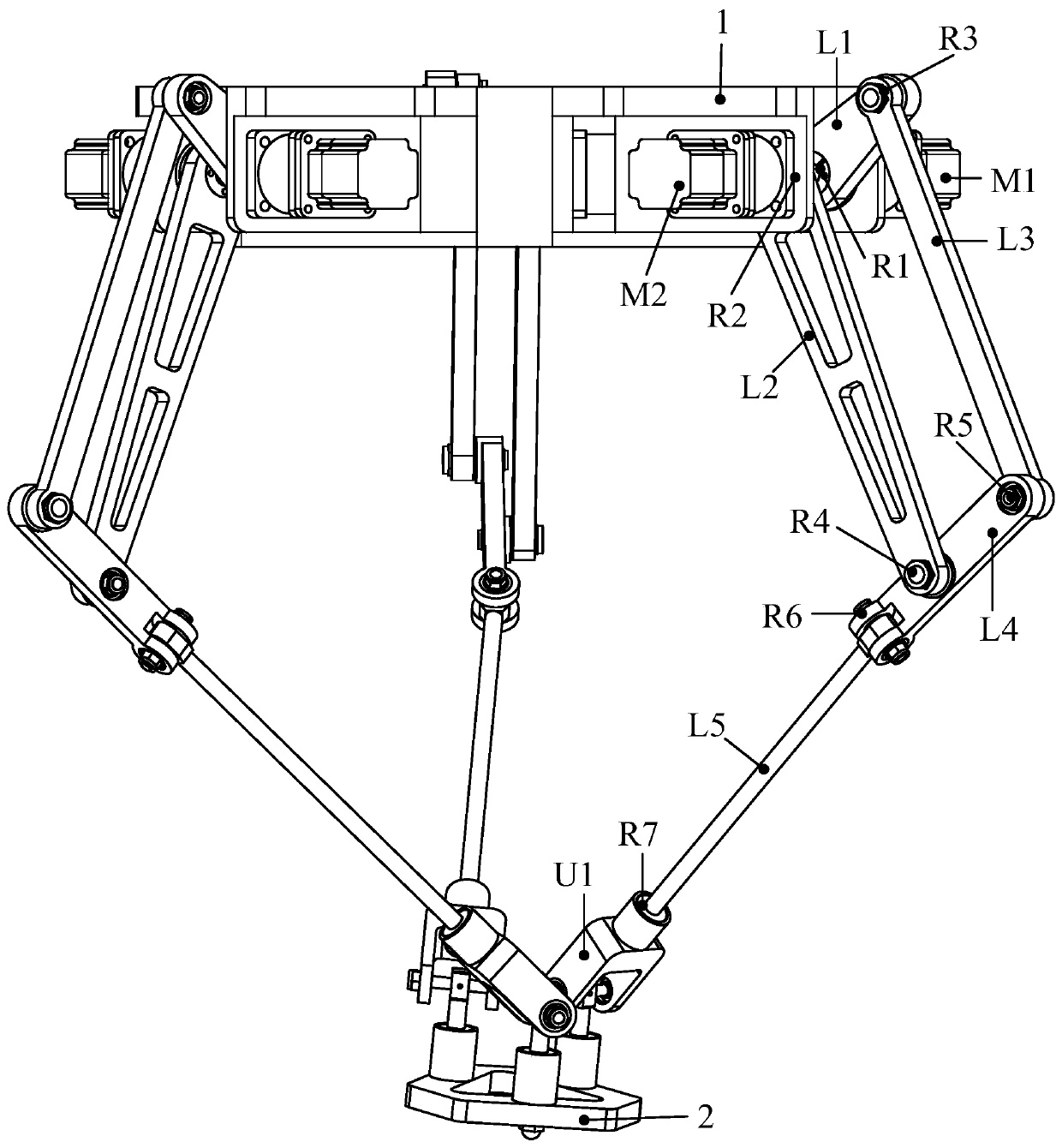
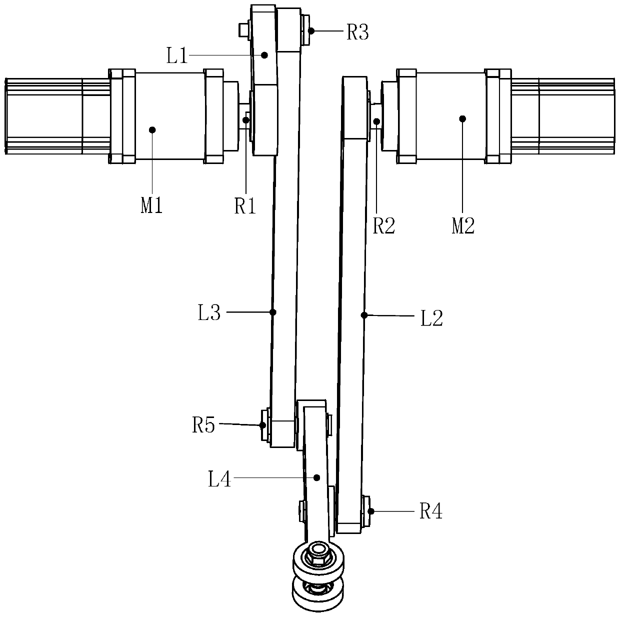
[0019] see figure 1 , 3, 4, a parallel robot with a large working space and low inertia, including a frame 1, a moving table 2, three identical and along the center of the frame between the connecting frame 1 and the moving table 2 The axis is evenly distributed around the branch; each branch from the frame 1 to the moving console 2 is a parallelogram coupling driving assembly, the sixth rotating joint assembly R6, the driven rod L5, the seventh rotating joint assembly R7, and the universal Hinge assembly U1; the parallelogram coupling drive assembly is connected with the driven rod L5 through the sixth rotating joint assembly R6, and the axis of the sixth rotating joint R6 is perpendicular to the center line of the driven rod L5; the driven The rod L5 is connected to the universal joint assembly U1 through the seventh rotary joint assembly R7, and the axis of the seventh rotary joint assembly R7 coincides with the center line of the driven rod L5; the universal joint assembl...

Embodiment 2

[0021] see figure 2 As shown, the difference between Embodiment 2 and Embodiment 1 is that the axis of the rotary joint in the universal joint assembly U1 close to the movable console 2 is parallel to or oblique to the plane where the movable console 2 is located.


PUM


Abstract

The invention discloses a parallel robot with a large working space and low inertia. The robot comprises a rack, a dynamic operation table, and three same branches connected between the rack and the dynamic operation table and uniformly and circumferentially distributed along a central axis of the rack, wherein each branch sequentially comprises a parallelogram coupling drive assembly, a sixth rotational joint assembly, a driven rod piece, a seventh rotational joint assembly and a universal hinge from the rack to the dynamic operation table. The parallel robot with the large working space andthe low inertia provided by the invention has the advantages that six drive motors are arranged on the rack and have no follow-up movement, and each branch is concise and compact in structure, so thatthe mechanism has the characteristics of low inertia, light weight, large working space, easiness in processing and manufacturing and the like, and has a favorable application prospect.

Description

technical field [0001] The invention relates to the technical field of advanced processing, manufacturing and assembly, in particular to a parallel robot with large working space and low inertia. Background technique [0002] Realizing the six-degree-of-freedom movement at the end of the parallel robot usually uses six-branch parallel connection or adds drive motors to the moving parts of the parallel three-, four-, and five-branch structures. The six-branch structure can arrange all the drive motors on the frame, but due to There are too many branches, which makes its manufacturing and assembly difficult and the movement space is small, such as the Stewart mechanism (6-SPS mechanism), and other six-degree-of-freedom parallel connections of three-, four-, and five-branch structures that load a part of the drive motor on the moving parts Robots inevitably lead to the problems of small movement space (branch interference) and large inertia (drive motor movement) in the six-deg...

Claims


Application Information

Patent Timeline
Patent Type & Authority Applications(China)
IPC IPC(8): B25J9/00B25J9/08B25J17/02
CPCB25J9/0048B25J9/08B25J17/0275
Inventor 曹文熬丁华锋饶坤
Owner CHINA UNIV OF GEOSCIENCES (WUHAN)
Learn More