Stop apparatus, and lens apparatus and image pickup apparatus having the same

a technology of stop apparatus and stop body, which is applied in the direction of optics, camera diaphragms, cameras, etc., can solve the problems of increasing the overall size of the stop body including the differential mechanism, inconvenient image shooting, etc., and achieves the effect of large rotational operation angl

Active Publication Date: 2017-06-06
CANON KK
View PDF8 Cites 0 Cited by
  • Summary
  • Abstract
  • Description
  • Claims
  • Application Information

AI Technical Summary

Benefits of technology

[0011]An object of the present invention is to provide a small-size stop apparatus that allows fine light quantity adjustment with a large rotational operation angle while having a stop aperture shape close to a circle formed by a large number of stop blades.
[0013]The present invention can provide a small size stop apparatus that enables fine adjustment of light quantity with a large rotational operation angle without an increase in the number of parts.

Problems solved by technology

However, it is difficult in the prior art apparatuses disclosed in Japanese Patent Application Laid-Open Nos. 2004-294678 and 2012-123299 mentioned above to achieve a large rotational operation angle while using a large number of stop blades because of a restrictive condition that interference of cam grooves that guide the drive pins of the stop blades with each other must be prevented.
Therefore, conventional stop apparatuses that use a large number of blades in order to achieve a stop aperture shape close to a circle do not allow fine adjustment of the light quantity using an operation member, causing inconvenience in image shooting.
H03-182709 mentioned above leads to a problem of increase in the overall size of the stop apparatus including the differential mechanism.

Method used


Image

  • Stop apparatus, and lens apparatus and image pickup apparatus having the same
  • Stop apparatus, and lens apparatus and image pickup apparatus having the same
  • Stop apparatus, and lens apparatus and image pickup apparatus having the same

Examples


second embodiment

[Second Embodiment]

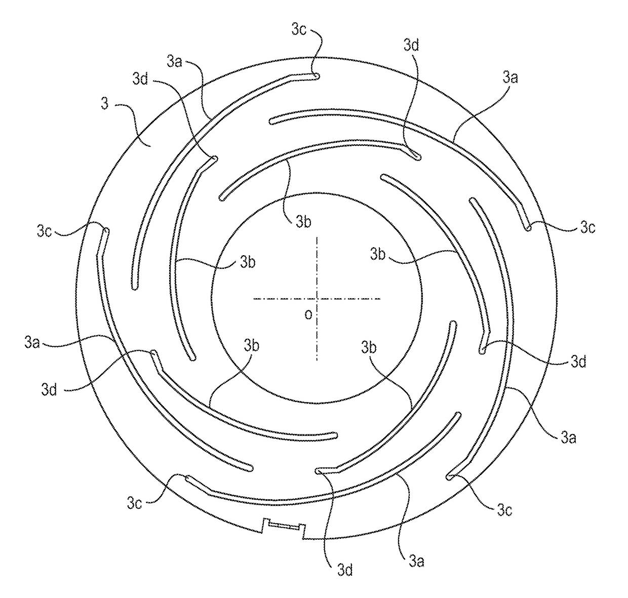
[0042]A stop mechanism according to the second embodiment differs from the first embodiment in the following respects. The second embodiment is characterized in that the end point of at least one of the cam grooves arranged at outer positions in the cam plate is located at a shorter distance from the optical axis position o (namely, closer to the optical axis position) than the start point of the cam grooves arranged at inner positions in the cam plate. Moreover, the second embodiment is also characterized in that the shapes of the stop blade plates are the same. Moreover, the second embodiment is also characterized in that two adjacent cam grooves that have start points equidistant from the optical axis o have different shapes.

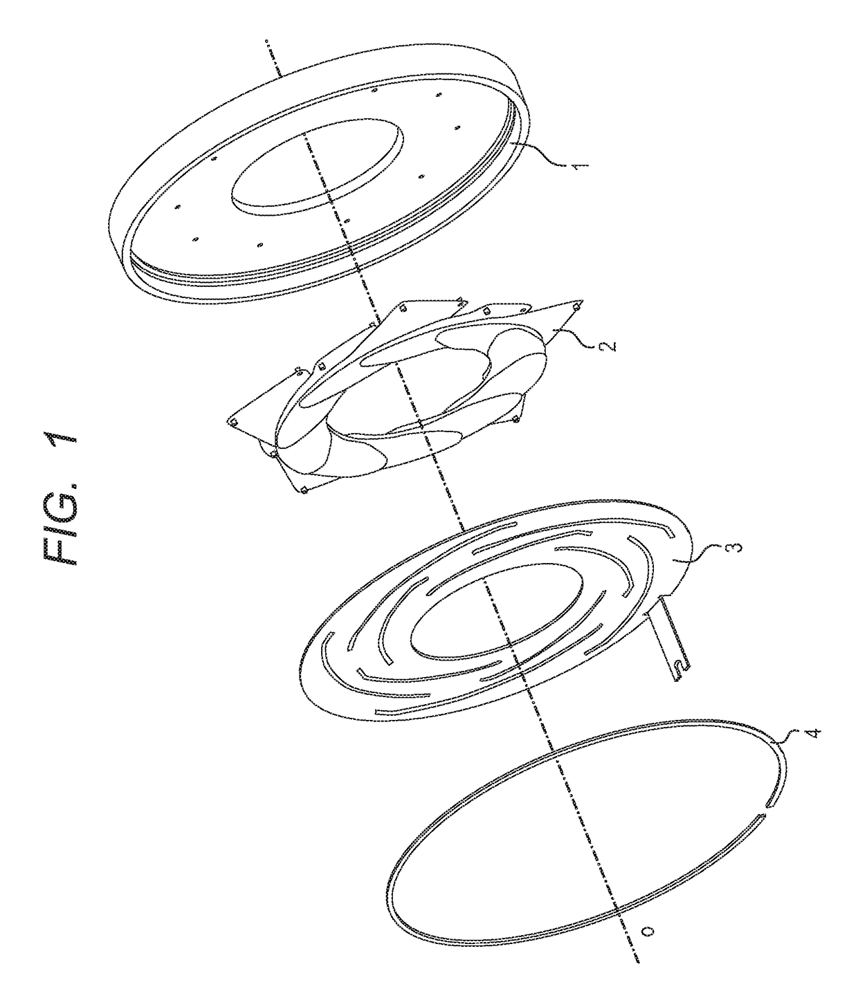
[0043]FIG. 8 is an exploded view of a stop apparatus of this embodiment. As shown in FIG. 8, the stop apparatus is composed of a stop blade support barrel (support member) 7, a plurality of stop blades 8, a cam plate 9, and a press washer 1...


PUM


Abstract

A stop apparatus includes blades each having a drive pin, a support member supporting pivot members of the blades, and a cam member having cams engaging with the drive pins. The blades form an aperture. The cam member includes cams of which the largest radial distances from the center of the aperture are different from each other. The blades include first blades and second blades. The radial distance from the center of the drive pins of the first blades and that of the drive pins of the second blades are different from each other in an open aperture state. The pivot members of the first and second blades are disposed at positions at a radial distance from the center shorter than the radial distance from the center of a drive pin having the longest radial distance from the center in the open aperture state among the drive pins.

Description

BACKGROUND OF THE INVENTION[0001]Field of the Invention[0002]The present invention relates to a stop apparatus used in a lens apparatus for image taking, in particular to a stop apparatus having an aperture diameter varied by rotational operation. The present invention also relates to a lens apparatus and an image pickup apparatus having such a stop apparatus.[0003]Description of the Related Art[0004]There has been known a stop apparatus including a plurality of stop blades each having a pivot axis arranged concyclically at regular angular intervals and having a stop aperture defined by edges of the overlapping stop blades, which is varied by rotations of the stop blades about their respective pivot axes. This type of stop apparatus includes a pivot pin and a drive pin provided for each of the stop blades, and the position of the drive pin relative to the pivot pin planted at a fixed position is guided by a cam groove provided in a disk-like cam plate.[0005]For example, Japanese Pat...

Claims


Application Information

Patent Timeline
Patent Type & Authority Patents(United States)
IPC IPC(8): G03B9/06
CPCG03B9/06G03B9/02
Inventor KAMO, DAICHI
Owner CANON KK
Why Eureka
Try Eureka