Stop apparatus, and lens apparatus and image pickup apparatus having the same

a technology of stop blades and stop blades, which is applied in the direction of optics, camera diaphragms, cameras, etc., can solve the problems of deteriorating the usability of the lens apparatuses in image taking, unable to finely adjust the light quantity using an operation member, and unable to achieve a large rotational operation angle while using a large number of stop blades. achieve the effect of large rotational operation angl

Active Publication Date: 2015-09-15
CANON KK
View PDF12 Cites 0 Cited by
  • Summary
  • Abstract
  • Description
  • Claims
  • Application Information

AI Technical Summary

Benefits of technology

[0010]In view of the above-described circumstances, an object of the present invention is to provide a compact stop apparatus allowing fine adjustment of the light quantity with a large rotational operation angle while having a stop aperture that is formed by a large number of stop blades to have a nearly circular shape.
[0012]According to the present invention there can be provided a compact stop apparatus allowing fine adjustment of the light quantity with a large rotational operation angle while having a stop aperture that is formed by a large number of stop blade to have a nearly circular shape.

Problems solved by technology

However, in the prior arts disclosed in the above-mentioned Japanese Patent Application Laid-Open Nos. 2004-294678 and 2012-123299, it is difficult to achieve a large rotational operation angle while using a large number of stop blades, because it is necessary to prevent the cam grooves for guiding the driving pins of the stop blade from interfering with each other.
Consequently, the conventional stop apparatuses that use a large number of stop blades in order to make the shape of the stop aperture close to a circle cannot allow fine adjustment of the light quantity using an operation member.
This deteriorates the usability of the lens apparatuses in image taking.
However, the use of this structure in a stop apparatus leads to a problem of increased overall size of the stop apparatus including the differential mechanism.

Method used


Image

  • Stop apparatus, and lens apparatus and image pickup apparatus having the same
  • Stop apparatus, and lens apparatus and image pickup apparatus having the same
  • Stop apparatus, and lens apparatus and image pickup apparatus having the same

Examples


first embodiment

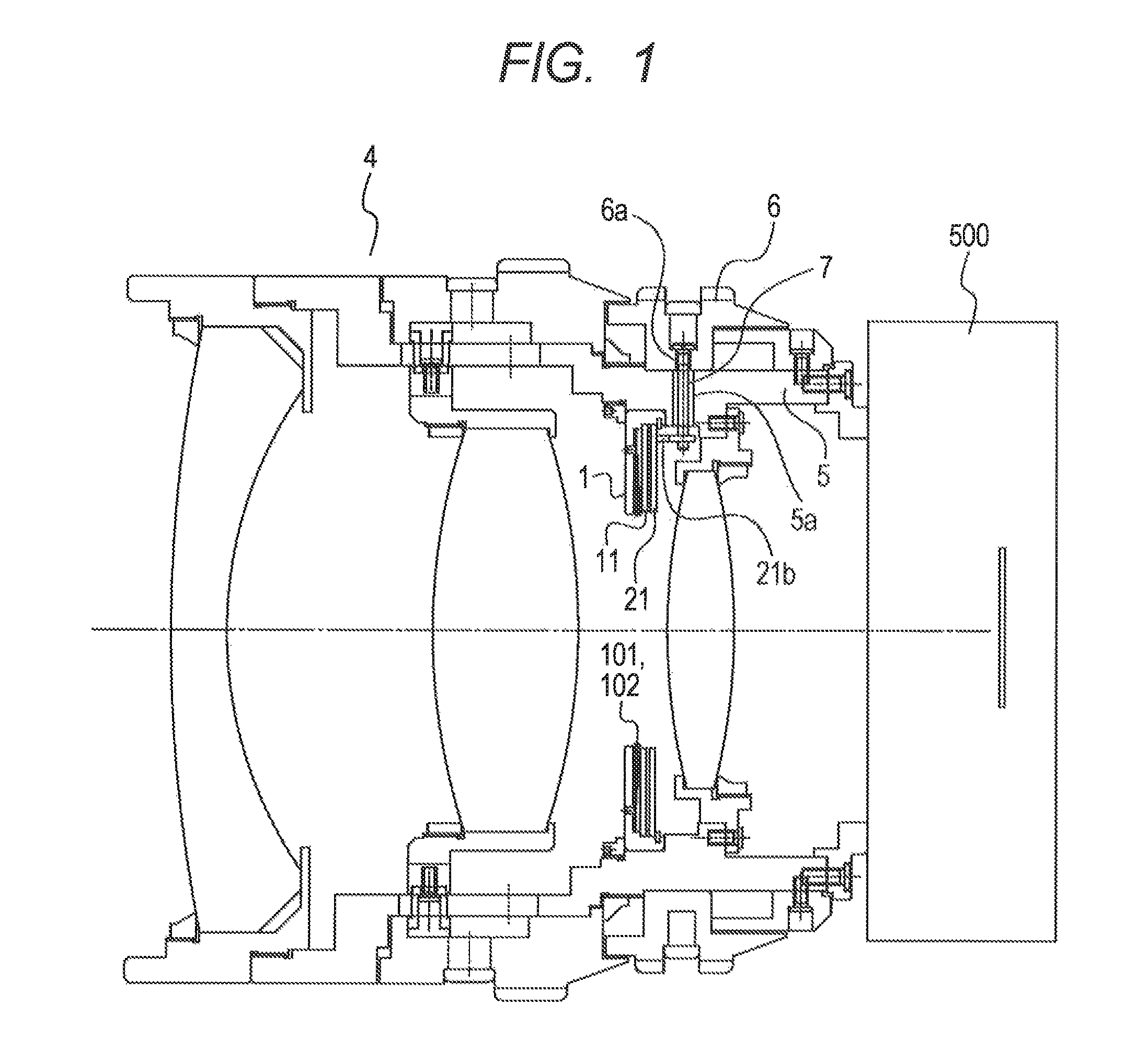
[0032]FIG. 1 is a side cross sectional view of an image pickup apparatus having a lens apparatus with a stop apparatus according to a first embodiment.

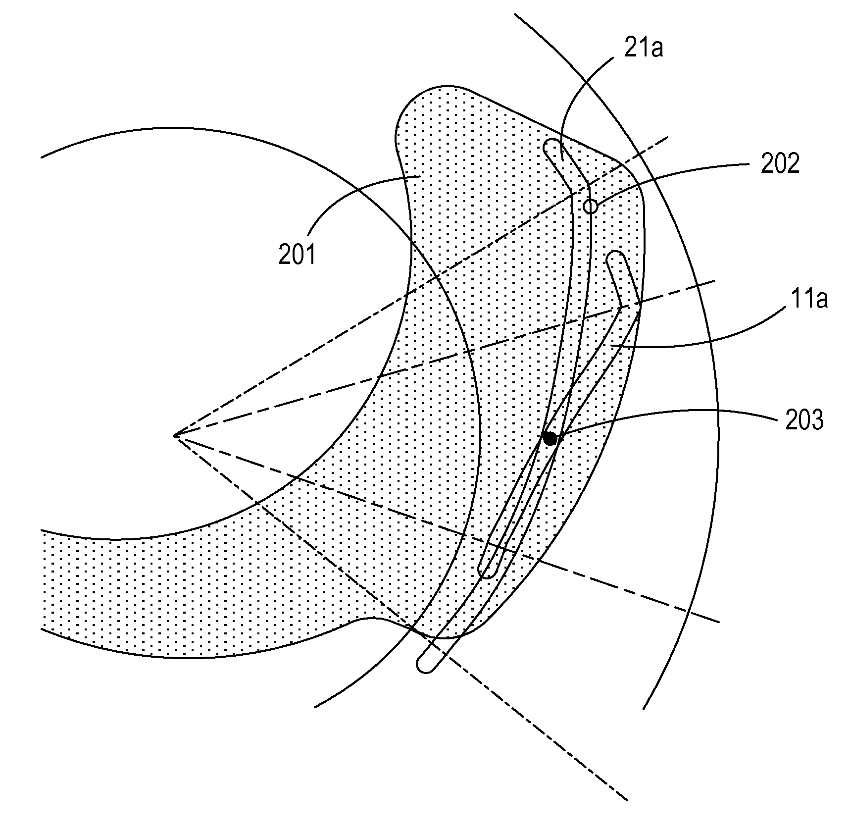
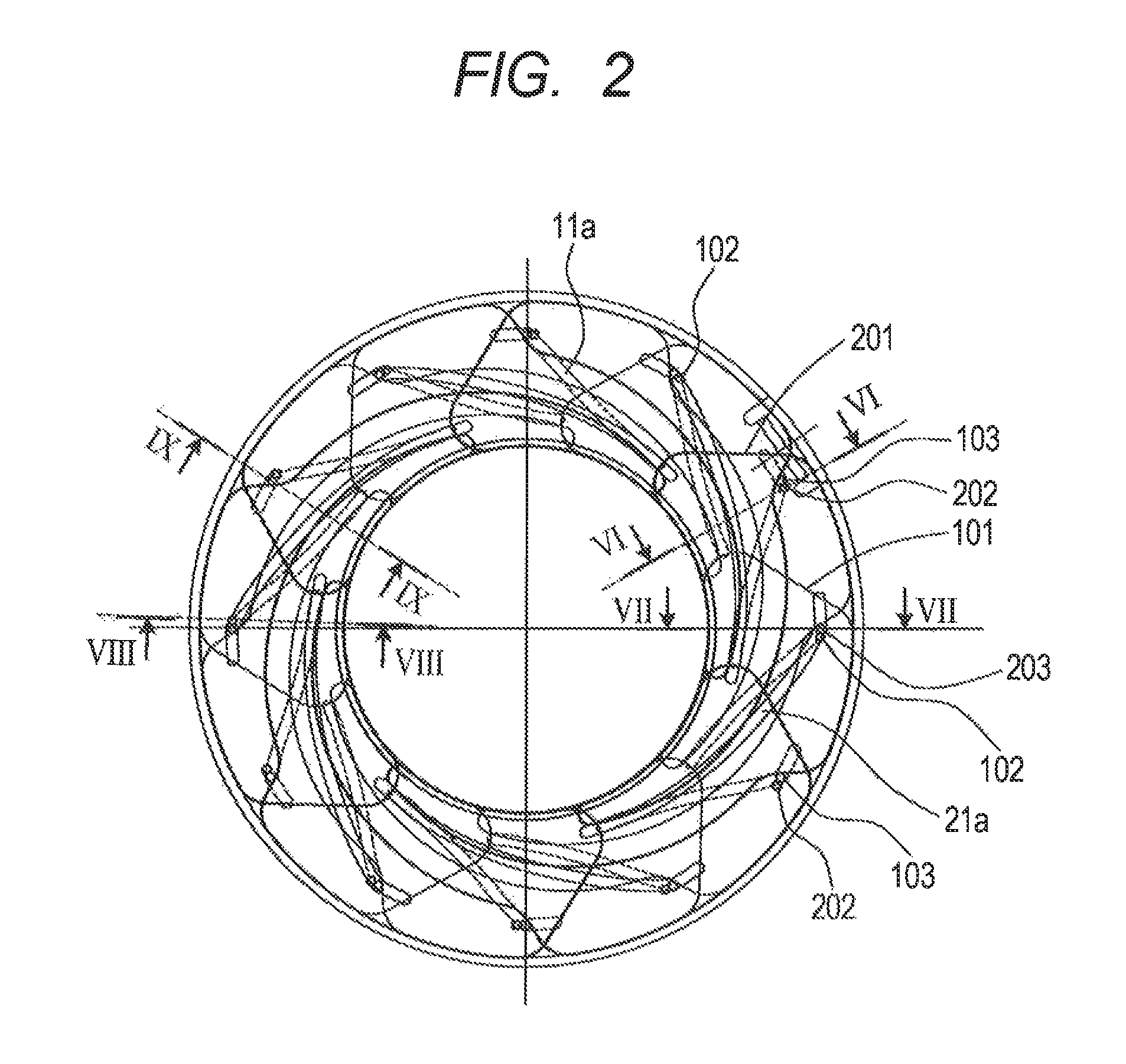
[0033]FIG. 2 is a perspective view showing relevant parts of the stop apparatus according to the first embodiment to which the present invention is applied. The relevant parts shown in FIG. 2 include first stop blades 100, second stop blades 200, a first cam plate (first cam member) 11, and a second cam plate (second cam member) 21. FIG. 3A is a view of the stop blades 101, 201 seen from the image pickup apparatus side. FIG. 3B is a view of the stop blades 101, 201 seen from the object side. FIG. 4 is a diagram showing the arrangement of cam grooves in the first cam plate 11. FIG. 5 is a diagram showing the arrangement of cam grooves in the second cam plate 21. FIG. 6 is a partial side cross sectional view taken along line VI-VI in FIG. 2. FIG. 7 is a partial cross sectional view taken along line VII-VII in FIG. 2. FIG. 8 is a partial...

second embodiment

[0057]FIG. 12 is a side cross sectional view of a stop apparatus according to a second embodiment to which the present invention is applied. Components same as those in the first embodiment are denoted by the same reference characters. In the following, what is different from the first embodiment will be described.

[0058]Each of second stop blades 210 is provided with a pivot pin 202 projecting from its object side surface and a driving pin 213 projecting from the opposite surface facing toward the image pickup apparatus. A nearly half object side part (lengthwise) of the driving pin 213 has a diameter smaller than the other part, and a roller (rolling member) 214 rotatably engages on the outer circumference of the small diameter part (shaft) 213a. The first cam plate 11 and the second cam plate 21 are arranged side by side on the image pickup apparatus side of two types of stop blades 100, 210. The first cam plate 11 and the second cam plate are smoothly rotatable relative to the st...

third embodiment

[0069]FIG. 13 is a partial side cross sectional view of a stop apparatus according to a third embodiment to which the present invention is applied. FIG. 13 is a partial side cross sectional view similar to FIG. 9 in the first embodiment, which is taken along line IX-IX in FIG. 2. Components same as those in the first embodiment are denoted by the same reference characters. In the following, what is different from the first embodiment will be described.

[0070]Each of first stop blades 110 and stop second blades 220 is provided with a pivot pin 102, 202 projecting from its object side surface and a driving pin 103, 203 projecting from the opposite surface facing toward the image pickup apparatus. The plate parts 111, 221 of these two types of stop blades have the same shape and are made of a non-magnetic material. The first cam plate 12 and the second cam plate 22 are arranged side by side on the image pickup apparatus side of two types of stop blades 110, 220. The first cam plate 12 a...


PUM


Abstract

A stop apparatus includes a stop operation member, a plurality of stop blades, each of which is provided with a pivot and a driving pin, a blade supporter that supports the stop blades in such a way that the stop blades are rotatable about the pivots of the respective stop blades, a first cam member provided with a first cam groove with which the driving pins of the respective stop blades engage, a second cam member provided with a second cam groove having a shape different from the first cam groove, and a driving force transmission member that transmits rotational driving force of the stop operation member to the second cam member. At least one of the driving pins engages with both the first cam groove and the second cam groove.

Description

BACKGROUND OF THE INVENTION[0001]1. Field of the Invention[0002]The present invention relates to a stop apparatus used in a lens apparatus for image taking and more particularly to a stop apparatus in which the aperture diameter is varied by a rotational operation. The present invention also relates to a lens apparatus and an image pickup apparatus having such a stop apparatus.[0003]2. Description of the Related Art[0004]There has been known heretofore a stop apparatus having a plurality of stop blades each having a pivot that are arranged in the same circumference at regular angular intervals so that a stop aperture defined by overlapping edges of the stop blades can be varied with swinging of the stop blades about the respective pivot shafts. In a typical stop apparatus of this type, each blade is provided with a pivot pin and a driving pin, and the position of the driving pin relative to the pivot pin, which is supported at a fixed position, is guided by a cam groove formed in a ...

Claims


Application Information

Patent Timeline
Patent Type & Authority Patents(United States)
IPC IPC(8): G03B9/02G03B9/06
CPCG03B9/06
Inventor SHIBASAKI, GOU
Owner CANON KK
Why Eureka
Try Eureka