
Autonomous cardiac implant of the "leadless capsule" type, with detection of atrial activity by analysis of the charging electric signal delivered by an energy harvesting module

Active Publication Date: 2019-05-23
CAIRDAC
View PDF0 Cites 5 Cited by
  • Summary
  • Abstract
  • Description
  • Claims
  • Application Information

AI Technical Summary

Benefits of technology

The patent describes a way to detect atrial activity without adding complexity to the device. It provides reliable information about the presence or absence of atrial contraction and accurately detects the time of occurrence of the contraction. This method reflects the physiological phenomenon of mechanical atrial contraction without introducing bias related to electro-mechanical delay.

Problems solved by technology

It hence suffers from the drawback that the ventricular stimulation is not synchronous with the atrium contraction, so that the stimulation rate does not adapt to the sinus rhythm at a given instant (sinoatrial rhythm).
But this mechanism provides no specific information about the atrium activity, which would make it possible in particular to determine whether or not the latter contracts, at which rate and at what time.
The problem is, in such a case, to be able to detect an atrial activity based on the single leadless capsule implanted in the ventricle, with no means nor possibility to directly collect, using an atrial lead, a signal reflecting an electrical activity of the atrium.
However, all these solutions remain complex to implement and, in practice, their reliability is often insufficient to detect the presence or not of an atrial activity with a high degree of certainty, and an accurate determination of the instant of occurrence of the atrial contraction.
The detection of an electrical activity indeed particularly suffers from various disturbances, artefacts and interferences.

Method used


Image

  • Autonomous cardiac implant of the "leadless capsule" type, with detection of atrial activity by analysis of the charging electric signal delivered by an energy harvesting module
  • Autonomous cardiac implant of the "leadless capsule" type, with detection of atrial activity by analysis of the charging electric signal delivered by an energy harvesting module
  • Autonomous cardiac implant of the "leadless capsule" type, with detection of atrial activity by analysis of the charging electric signal delivered by an energy harvesting module

Examples


Embodiment Construction

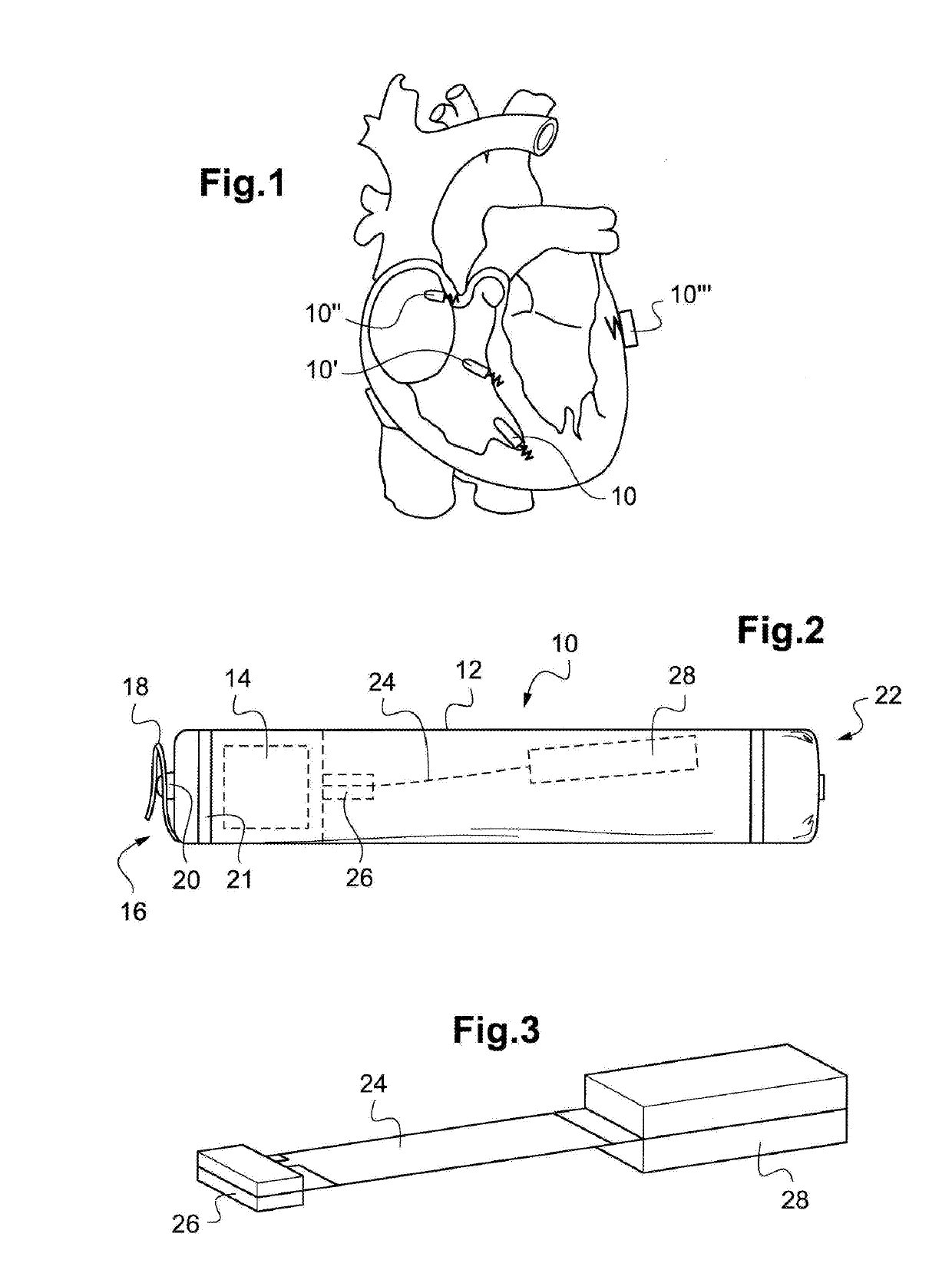
[0060]An exemplary embodiment of the device of the invention will now be described.

[0061]As regards its software aspects, the invention may be implemented by a suitable programming of the control software of a known cardiac stimulator device, for example a stimulator of the endocavitary leadless capsule type.

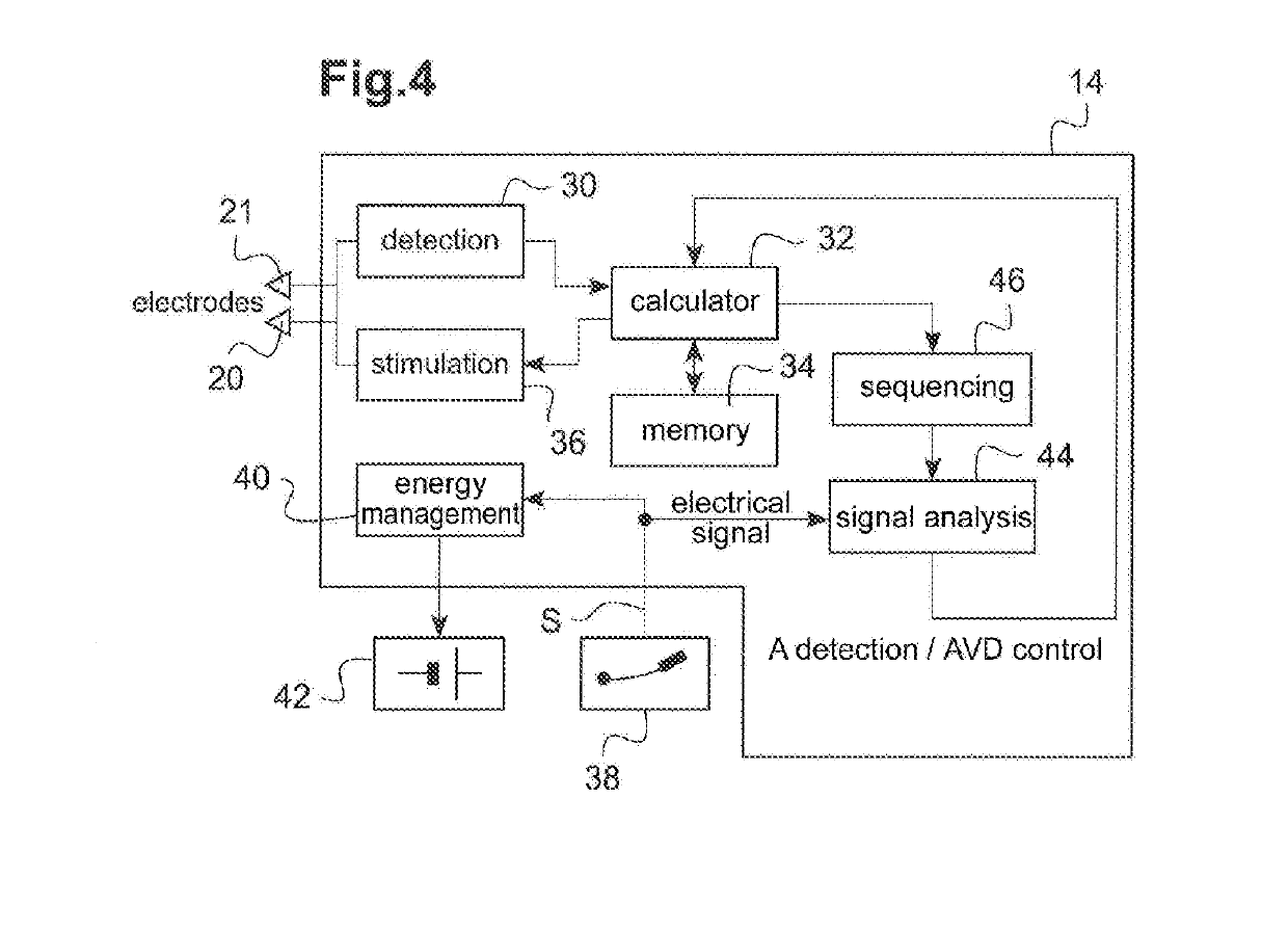
[0062]These devices include a programmable microprocessor or microcontroller coupled to circuits for receiving, shaping and processing electrical signals collected by electrodes arranged on the capsule, at least one of which is in contact with the myocardium, and delivering stimulation pulses to these electrodes. The adaptation of these devices to make the invention is within the reach of the one skilled in the art, and won't be described in detail. In particular, the software programs stored in memory and executed may be adapted or used to implement the functions of the invention that will be described hereinafter.

[0063]The method of the invention is indeed mainly implemented b...


PUM


Abstract

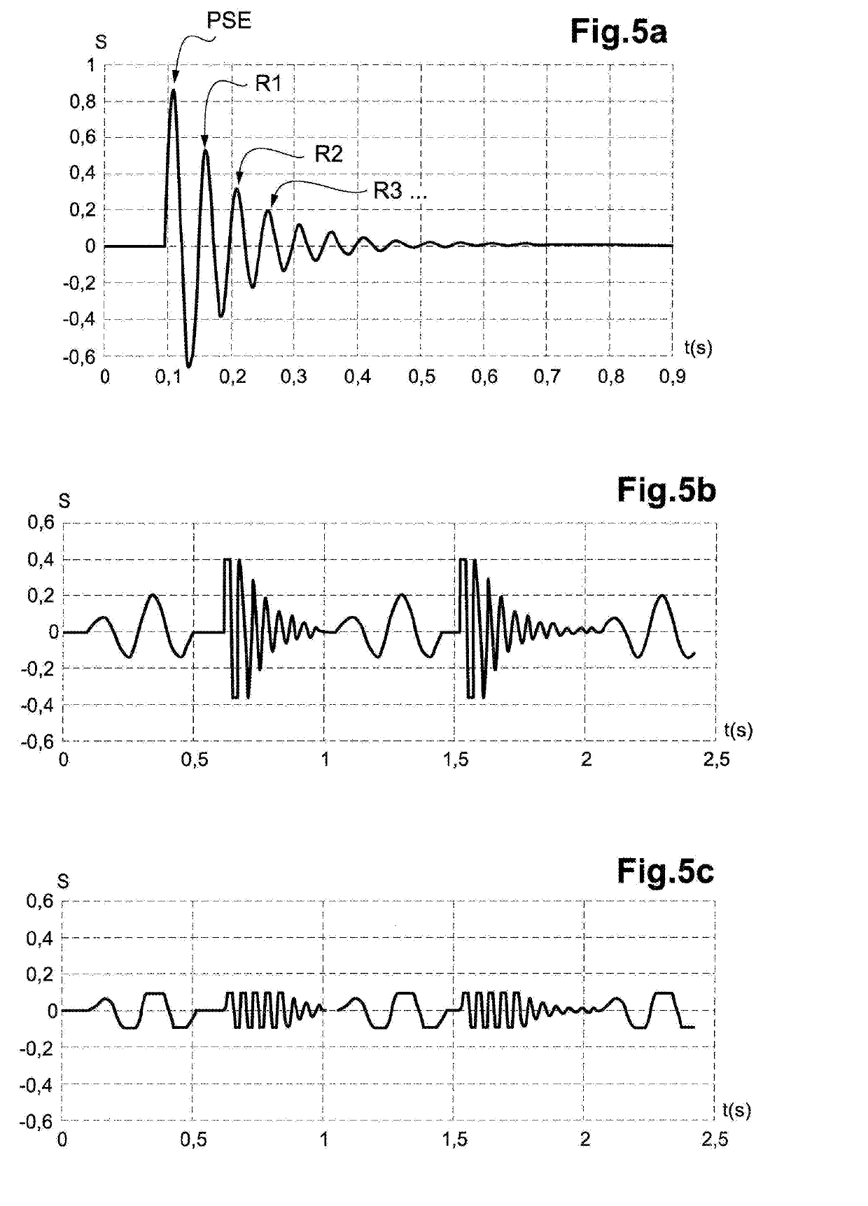
An energy harvester converts into electrical energy the external stresses applied to the implant at the heartbeat rhythm. This harvester includes an inertial unit and a transducer delivering an oscillating electrical signal that is rectified and regulated for powering the implant and charging an energy storage component. The instantaneous variations of this electrical signal are analyzed in a detection window following or preceding a ventricular contraction, to obtain atrial activity information representative of the atrium contribution to the electric signal, in particular information about the presence / absence of a spontaneous atrial contraction, and / or parameters making it possible to determine an atrioventricular delay to be applied if the ventricle has to be stimulated.

Description

CROSS REFERENCE TO RELATED APPLICATIONS[0001]This application claims priority under 35 U.S.C. § 119(a) to French Patent Application Serial Number 1761034, filed Nov. 22, 2017, the entire teachings of which are incorporated herein by reference.BACKGROUND OF THE INVENTIONField of the Invention[0002]The invention relates to an active implantable medical device (AIMD), in particular cardiac implants for monitoring the myocardium activity and delivering stimulation, resynchronization or defibrillation pulses in case of rhythm disorder detected by the device, and more particularly to those devices which incorporate a self-powering system.Description of the Related Art[0003]An AIMD which incorporates a self-powering system includes a mechanical energy harvesting device associated with an integrated energy storage component, such as a rechargeable battery or a high-performance capacitor. The harvesting device, also called harvester or scavenger, collects the mechanical energy resulting from...

Claims


Application Information

Patent Timeline
IPC IPC(8): A61N1/378A61N1/375A61N1/365A61N1/368
CPCA61N1/3785A61N1/3756A61N1/37512A61N1/37518A61N1/36507A61N1/3684A61N1/3682A61N1/3956A61B5/686A61B5/6869A61N1/025H02N2/186H10N30/306
Inventor BONNET, JEAN-LUC
Owner CAIRDAC
Learn More