
Sit-to-stand wheelchair

Active Publication Date: 2019-05-09
DOWDING TOOL PROD LLC
View PDF0 Cites 7 Cited by
  • Summary
  • Abstract
  • Description
  • Claims
  • Application Information

AI Technical Summary

Benefits of technology

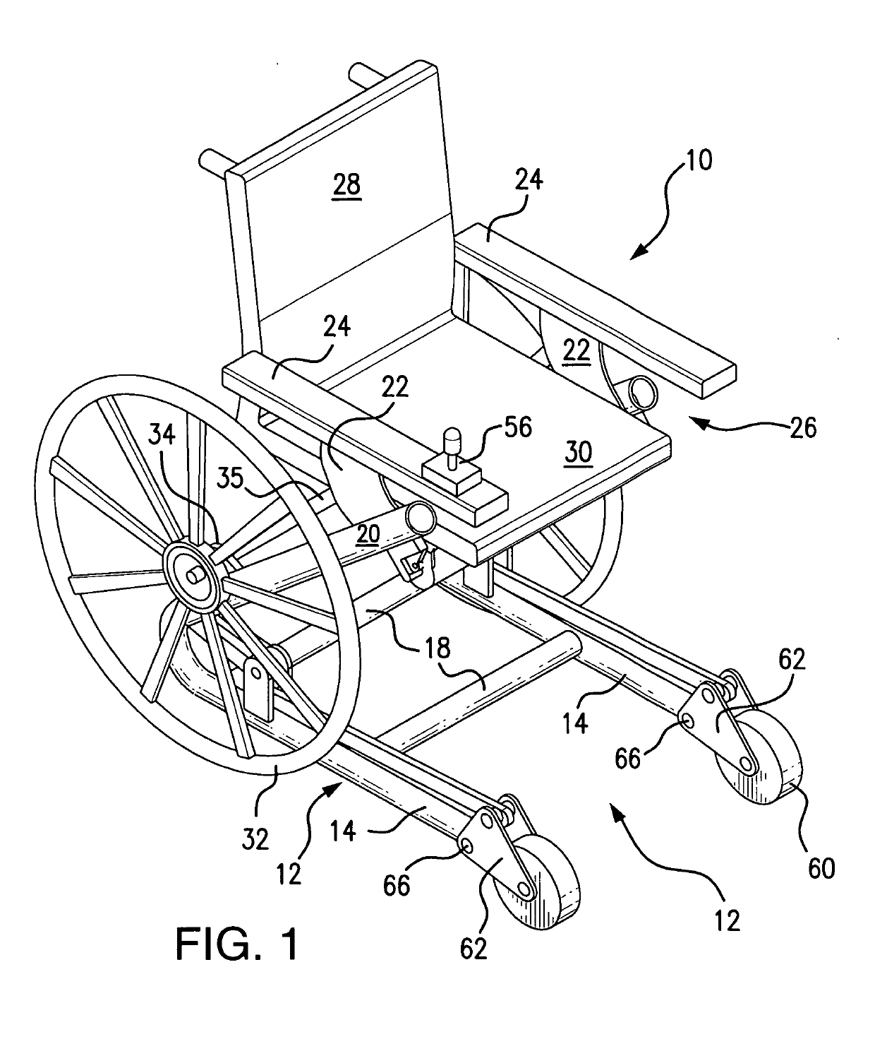
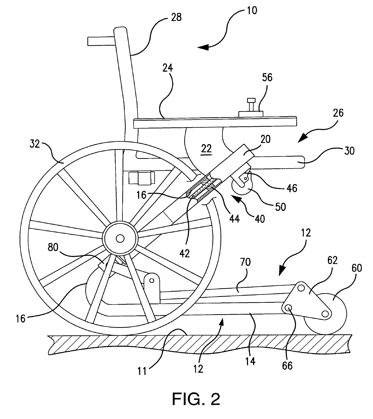
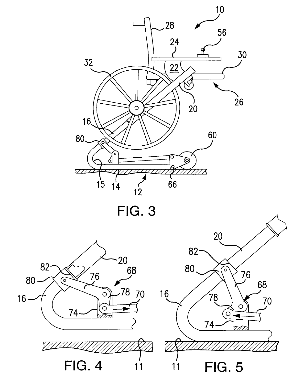
The present invention is a wheelchair assembly that can elevate a patient to a standing position with solid support. Unlike previous designs, the present invention avoids the use of multiple linkages and pivot points. Instead, it uses a low-cost, high-strength telescopic power actuator that encapsulates a simple, low-cost operative movement. The wheelchair can move from a retracted mobile position to an extended position on a surface or ground, providing stable support for the patient during the transition to a standing position. The unique design features a simple, low-cost structure and is easy to use and operate.

Problems solved by technology

However, such prior devices are illustrated by expensive, complex systems that often included a plurality of linkages, cables, pulleys, etc.
On belief, none of the prior art developments have resulted in a commercially acceptable mobile wheelchair with a sit-to-stand capability.
Those developments appear to lack the desirable low cost, as well as the simplicity, strength and / or reliability to be commercially acceptable.

Method used


Image

  • Sit-to-stand wheelchair
  • Sit-to-stand wheelchair
  • Sit-to-stand wheelchair

Examples


second embodiment

[0047]the front wheel system is the caster system 64 shown in FIGS. 7-10. Here, the caster unit 64 has a linkage 84 pivotally connected to the elongated members 14 by a pivot pin 66. This pivotal linkage 84 is also connected by a rod 96 which extends upward within a cylinder 90 that is pivotally connected to upper telescopic member 20. As this upper telescopic member 20 is retracted downward, the cylinder 90 is pushed downward as shown in FIGS. 7 and 9. A plug welded abutment 94 within the cylinder 90 slides over the rod 96 to engage a donut 98 welded or fixed on the rod 96 to force link 84 clockwise and the caster unit 64 downward raising the front base 12 of the wheel chair 10 to make it mobile. Reverse movement of the screw actuator 40 raises upper telescopic member 20 which draws the cylinder 90 upward to permit the caster unit 64 to rotate counterclockwise and lower the wheel chair 10 to the floor to solidly support the chair as the patient is elevated to a standing position.

third embodiment

[0048]these inventions is reflected in FIGS. 11 through 13. FIG. 11 illustrates two horizontal base supports 112 with a telescopic linear actuator 114 vertically mounted on each support 112 in a manner sufficiently rigid to support the wheelchair and a person. As shown in FIG. 13, the extendable linear actuator 114 comprises a lower tubular section 115 and an upper tubular section 118 driven, preferably, by a 12 volt DC motor 120 through a gear assembly 121 mounted just above the motor 120. Such DC operated linear actuators are commercially available and sources include, for example, those provided by JWF Technologies of Fairfield, Ohio or Saco-USA Inc. of Rockford Ill. sold under the name “Linear Actuator 808”. This purchased actuator of FIGS. 11-13 provides vertical movement of some 350 mm or approximately 13 inches and includes rigid aluminum tubular members 115 and 118. Persons skilled in the art will appreciate that such tubular members may be separately manufactured of either ...


PUM


Abstract

This invention comprises a low cost, high strength sit-to-stand wheel chair assembly. It is comprised of a base with an upward extension formed of a linear actuator mounted within telescopic members. The telescopic members carry large wheels together with a linkage operated front wheels that are mounted on the forward position of the base. A power linear actuator assembly causes the telescopic members to extend and retract to move the wheelchair assembly from the mobile position to a raised position that permits the base to engage the floor surface and to assist the patient to move from a sitting position to a standing position.

Description

[0001]This is a non-provisional U.S. Patent Application which claims the benefit of Provisional Application No. 62 / 707,595 entitled SIT-TO-STAND WHEELCHAIR filed Nov. 9, 2017, the entirety of which is incorporated in this application as if fully set forth herein.BACKGROUND OF THE INVENTION[0002]Field of Invention. This application is directed to a mobile device for persons with limited ambulatory ability. Such patients present mobility and ambulatory problems to themselves, to hospital and clinic technicians and to the personnel of senior living and assisted care facilities. Such problems include difficulty of moving from a bed to a mobile wheelchair and then to an imaging center where they must stand or position themselves on a table for an X-ray, computed tomography scan (CT scan) or a magnetic resonance image (MRI). Similarly, in senior living facilities and assisted living facilities, patients must often be moved from beds to shower facilities and to food service facilities.[000...

Claims


Application Information

Patent Timeline
IPC IPC(8): A61G5/14A61G5/10
CPCA61G5/14A61G5/1059A61G5/104A61G5/128A61G7/1017B24B23/005B24B23/02
Inventor DOWDING, MAURICE H.
Owner DOWDING TOOL PROD LLC
Learn More