Method for manufacturing clad material
a technology of clad plate and clad plate, which is applied in the direction of non-electric welding apparatus, metal-working apparatus, electrical apparatus, etc., can solve the problems of reducing the corrosion resistance of clad plate, and achieve the effect of reducing or preventing the generation of cracks in the ni plating layer
- Summary
- Abstract
- Description
- Claims
- Application Information
AI Technical Summary
Benefits of technology
Problems solved by technology
Method used
Image

Examples
first embodiment
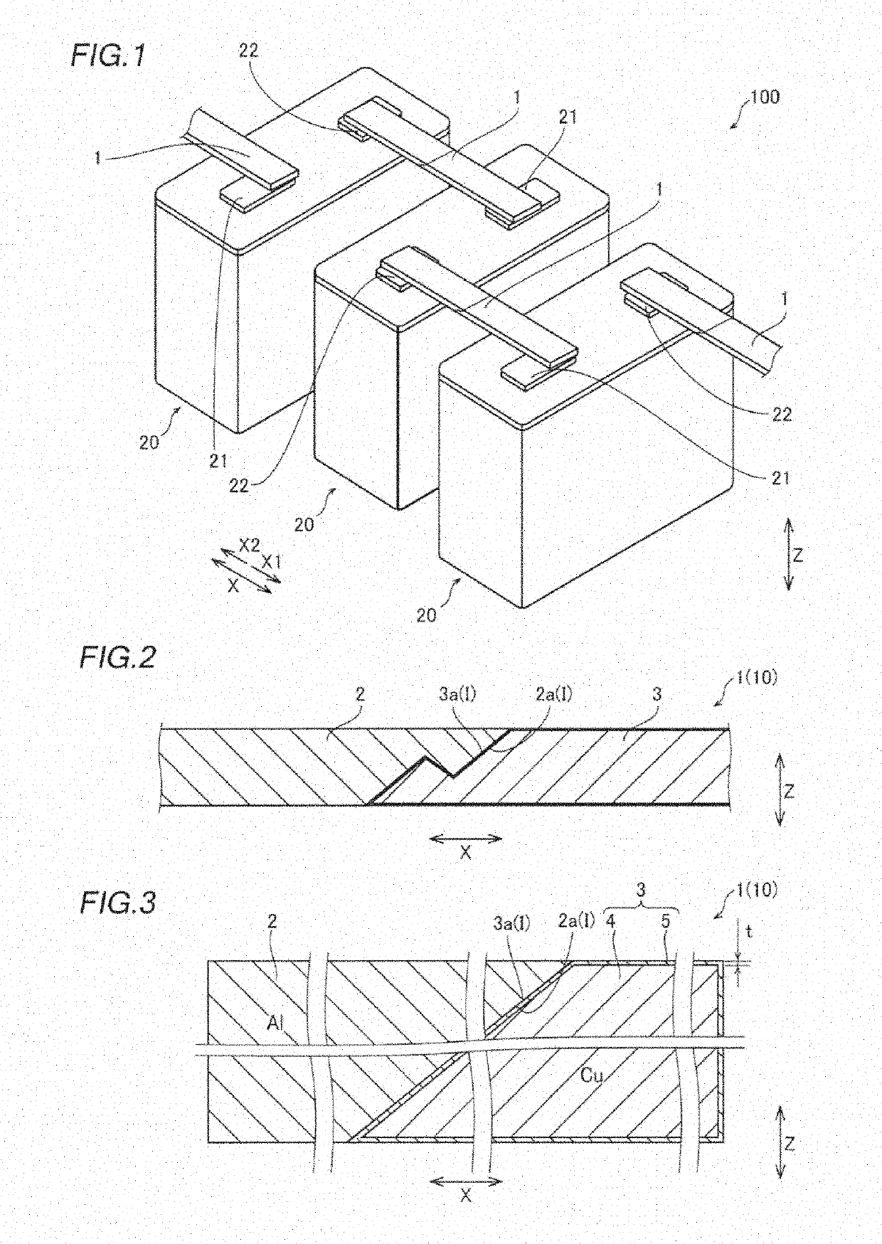
[0057]The structure of an assembled battery 100 according to a first embodiment of the present invention in which a clad material 10 is used as a bus bar 1 is now described with reference to FIGS. 1 to 3.
[0058]The structure of the assembled battery 100 according to the first embodiment of the present invention is described.
[0059]As shown in FIG. 1, in the assembled battery 100 according to the first embodiment of the present invention, a plurality of lithium-ion secondary batteries 20 are electrically connected to each other by a plurality of flat plate-like bus bars 1.
[0060]A positive electrode terminal 21, which is made of Al, of a predetermined lithium-ion secondary battery 20 is welded (bonded) to one end (an end on the X1 side) of the bus bar 1 in a direction X. Furthermore, a negative electrode terminal 22, which is made of Cu, of a lithium-ion secondary battery 20 adjacent to the predetermined lithium-ion secondary battery 20 is welded to the other end (an end on the X2 side)...
second embodiment
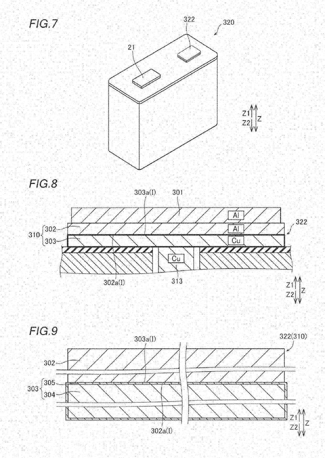
[0088]The structure of a lithium-ion secondary battery 320 according to a second embodiment of the present invention in which a clad material 310 is used as a negative electrode terminal 322 is now described with reference to FIGS. 7 to 9. The negative electrode terminal 322 is an example of a “terminal” in the claims.
[0089]As shown in FIG. 7, the lithium-ion secondary battery 320 according to the second embodiment of the present invention includes a positive electrode terminal 21 and the negative electrode terminal 322. Similarly to the positive electrode terminal 11 and the negative electrode terminal 12 (see FIG. 1) according to the aforementioned first embodiment, the positive electrode terminal 21 and the negative electrode terminal 322 are respectively welded (bonded) to one end and the other end of a bus bar 301 (see FIG. 8) made of Al.
[0090]As shown in FIGS. 8 and 9, the negative electrode terminal 322 is made of a two-layered clad material 310 in which a plate-shaped Al por...
first example
[0103]A first example conducted to confirm the effect of the present invention is now described with reference to FIGS. 13 to 24. In the first example, Ni-plated Cu materials were actually made under different heat treatment conditions and different rolling conditions (rolling reductions). Then, the surface conditions of Ni plating layers in the Ni-plated Cu materials were observed and compared with each other, and quantitative analysis of gases released from the Ni-plated Cu materials was performed.
[0104]Specifically, Cu materials each having a thickness of 1.67 mm, 2.5 mm, or 5 mm and made of oxygen-free copper were prepared. Then, an electroplating treatment using a Watts bath was performed such that a Ni plating layer with a thickness of 5 μm was formed on the entire surface of each of the Cu materials. At this time, the current density and the plating time in the electroplating treatment are adjusted such that the Ni plating layer with a thickness of 5 μm was formed. Thus, a Ni...
PUM
| Property | Measurement | Unit |
|---|---|---|
| holding temperature | aaaaa | aaaaa |
| holding temperature | aaaaa | aaaaa |
| holding temperature | aaaaa | aaaaa |
Abstract
Description
Claims
Application Information
 - R&D
- Intellectual Property
- Life Sciences
- Materials
- Tech Scout
- Unparalleled Data Quality
- Higher Quality Content
- 60% Fewer Hallucinations
Browse by: Latest US Patents, China's latest patents, Technical Efficacy Thesaurus, Application Domain, Technology Topic, Popular Technical Reports.
© 2025 PatSnap. All rights reserved.Legal|Privacy policy|Modern Slavery Act Transparency Statement|Sitemap|About US| Contact US: help@patsnap.com