Liquid crystal display device, side backlight unit, lamp reflector and reflection member

a technology of liquid crystal display device and backlight unit, which is applied in the direction of identification means, lighting and heating apparatus, instruments, etc., can solve the problems of increasing the conspicuousness of bright lines, reducing the distance between the screen and the lamp, and generating periodic bright lines from the lamp. , to achieve the effect of reducing or preventing the generation of bright lines

Inactive Publication Date: 2007-05-01
IBM CORP
View PDF8 Cites 2 Cited by
  • Summary
  • Abstract
  • Description
  • Claims
  • Application Information

AI Technical Summary

Benefits of technology

[0009]In this connection, one objective of the present invention is to provide a side backlight unit and a liquid crystal display device that are capable of reducing or preventing the generation of bright lines.
[0012]Here, the lamp reflector is configured in such a manner that a sheet having specified rigidity, made of brass or stainless steel (SUS) or the like, is bent in an approximately U-character shape, and a light reflection layer is formed on an inner circumference surface thereof. The lamp reflector serves as a protector for the lamp and has a role in making the light emitted from the lamp incident onto the light guide plate efficiently. In general, a light reflection layer may be formed by using a sheet coated with a reflective material, such as silver (Ag) or aluminum (Al), or a resin sheet containing a white pigment. In many cases, a sheet coated with Ag (an Ag sheet) is used as a reflection layer since Ag has high reflectivity.
[0016]According to the liquid crystal display device of the present invention, since the thickness of the transparent protective layer is set at less than 5 micrometers, the generation of the bright lines can be reduced or prevented.
[0019]As apparent from the above description, the present invention adopts a configuration that reduces the influence of light incident onto the light guide plate through the transparent protective layer formed on the lamp reflector. Hence, according to the present invention, provided is a side backlight unit, comprising: a light guide plate including at least one incident surface and an emitting surface for emitting light incident from the incident surface; a lamp disposed along the incident surface of the light guide plate; and a lamp reflector including an accommodation space for accommodating the lamp, a light reflection layer for reflecting light irradiated from the lamp and guiding the light to the incident surface of the light guide plate, and a transparent protective layer for protecting the light reflection layer, the light reflection layer and the transparent protective layer being formed on an inner circumference surface of the lamp reflector, wherein the transparent protective layer is deposited on the light reflection layer after the light reflection layer is deposited on a reflector body.

Problems solved by technology

However, although the luminance distribution is made even, in prior art LCD devices using side backlight units, a problem occurs in that bright lines are generated at periodic positions from the lamp.
Moreover, as the size of screens has increased, the distance from the screen to the lamp has decreased, and the bright lines have become increasingly conspicuous.
However, the current situation is that the generation of the bright lines K has not yet been completely eliminated, and this problem remains to be solved.

Method used


Image

  • Liquid crystal display device, side backlight unit, lamp reflector and reflection member
  • Liquid crystal display device, side backlight unit, lamp reflector and reflection member
  • Liquid crystal display device, side backlight unit, lamp reflector and reflection member

Examples


Embodiment Construction

[0038]Hereinbelow, description will be made for the present invention based on an embodiment with reference to the accompanying drawings.

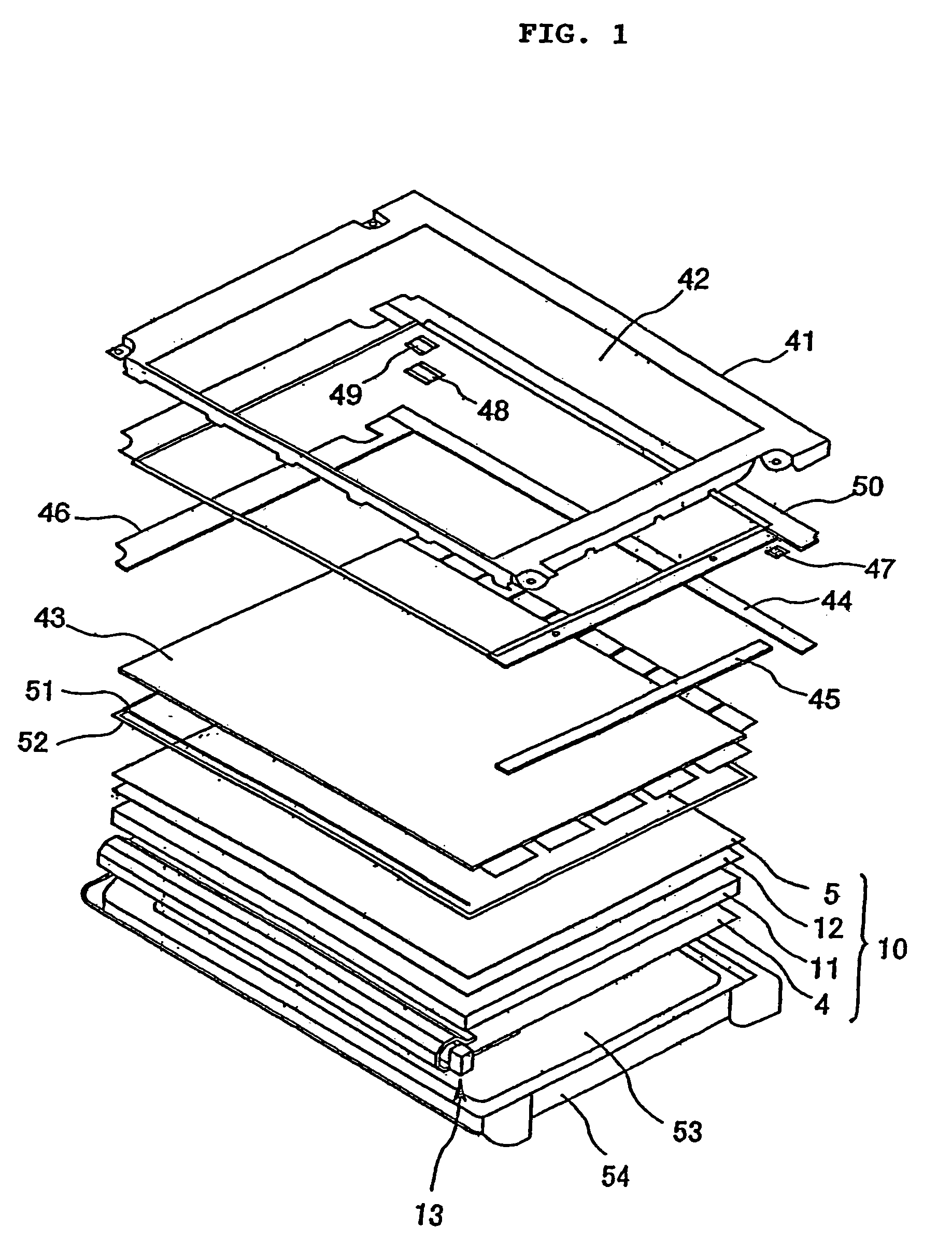
[0039]FIG. 1 is a perspective view for explaining an entire configuration of the liquid crystal display device in this embodiment. A reference numeral 41 denotes a metal shield case for forming an upper frame, which forms a display window 42 defining an effective screen of a liquid crystal display module. A numeral 43 denotes a liquid crystal display panel, in which thin film transistors (TFTs), each having source / drain electrodes, a gate electrode, an amorphous silicon layer and the like deposited thereon, and color filters are laminated between two glass substrates. On the liquid crystal display panel 43, a drain circuit substrate 44, a gate circuit substrate 45 and an interface circuit substrate 46 are formed, and furthermore, joiners 47, 48 and 49 are provided for joining the circuit substrates. These circuit substrates 44, 45 and 46 are fixed ...


PUM

PropertyMeasurementUnit
refractive indexaaaaaaaaaa
angleaaaaaaaaaa
thicknessaaaaaaaaaa

Abstract

A liquid crystal display (LCD) device having a side backlight unit that minimizes or eliminates extraneous bright lines on the LCD panel. The side backlight unit includes a lamp reflector and lamp disposed on a light incident side surface of a light guide plate. A light reflection layer is formed on the inner surface of the lamp reflector, and a transparent protective layer is formed on the reflection layer. The transparent protective layer has a thickness less than 5 micrometers. The lamp reflector has arm portions that sandwich the light guide plate on the front and back surfaces at the lamp side of the light guide plate. A light transmission region between the arm portions of the lamp reflector and the front and back surfaces of the light guide plate has a thickness less than 5 micrometers.

Description

CROSS-REFERENCE TO RELATED PATENT APPLICATIONS[0001]This Patent Application is a Divisional Patent Application of U.S. patent application Ser. No. 10 / 056,388, filed on Jan. 24, 2002 now abandoned.FIELD OF THE INVENTION[0002]The present invention relates to a reflection member, more particularly to a lamp reflector for use in a side backlight unit in a liquid crystal display (LCD) device.BACKGROUND OF THE INVENTION[0003]A liquid crystal display (LCD) device has become remarkably widespread for use as an image display device for a personal computer and other various monitors. Generally, a liquid crystal display device is configured in such a manner that a backlight unit is provided as a planar light source for illumination, disposed on a backside of a liquid crystal display panel, and so that a liquid crystal surface having a specified area is irradiated on the whole with even brightness, thus enabling visualization of an image formed on the liquid crystal surface.[0004]The backlight ...

Claims


Application Information

Patent Timeline
Patent Type & Authority Patents(United States)
IPC IPC(8): G02F1/1335G02B5/02F21V8/00F21Y103/00G02B5/08G02F1/13357G09F9/00
CPCG02B6/0031G02B6/0086G02F1/133615
Inventor KATSU, YOSHIHIROSUZUKI, MASARUNOGUCHI, MICHIKAZUNISHIKAI, AKIKO
Owner IBM CORP
Why Eureka
Try Eureka