
Multilayer ceramic capacitor

a ceramic capacitor and multi-layer technology, applied in the direction of fixed capacitors, stacked capacitors, fixed capacitor details, etc., can solve the problems of stress and mechanical strain, increase manufacturing costs, etc., and achieve the effect of reducing or preventing the generation of “acoustic noise” and low cos

Active Publication Date: 2021-10-28
MURATA MFG CO LTD
View PDF4 Cites 0 Cited by
  • Summary
  • Abstract
  • Description
  • Claims
  • Application Information

AI Technical Summary

Benefits of technology

This patent is about reducing or preventing the generation of "acoustic noise" in multilayer ceramic capacitors at a low cost. The technical effect is the provision of affordable solutions for reducing or eliminating acoustic noise in multilayer ceramic capacitors.

Problems solved by technology

However, since the dielectric layers have piezoelectric and electrostrictive properties, stress and mechanical strain occur when an electric field is applied.
Such stress and mechanical strain cause vibration, which is then transmitted to a substrate on which the multilayer ceramic capacitor is mounted.
However, providing such an interposer increases the manufacturing cost, and processing for providing the interposer is also required.

Method used


Image

  • Multilayer ceramic capacitor
  • Multilayer ceramic capacitor
  • Multilayer ceramic capacitor

Examples


Embodiment Construction

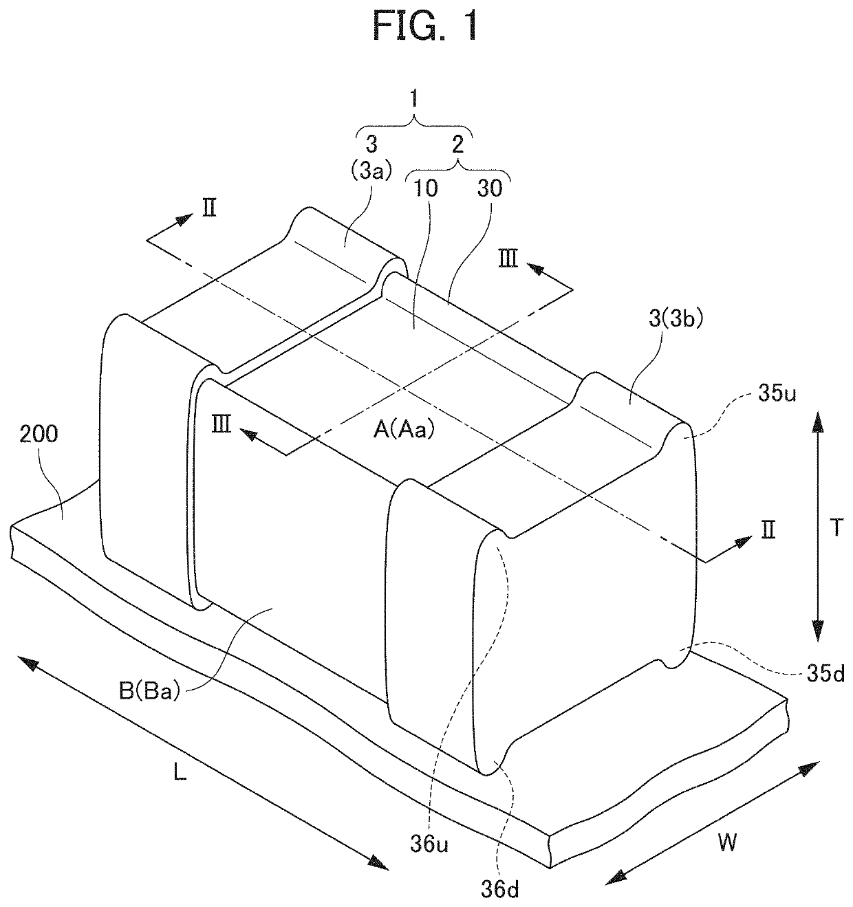
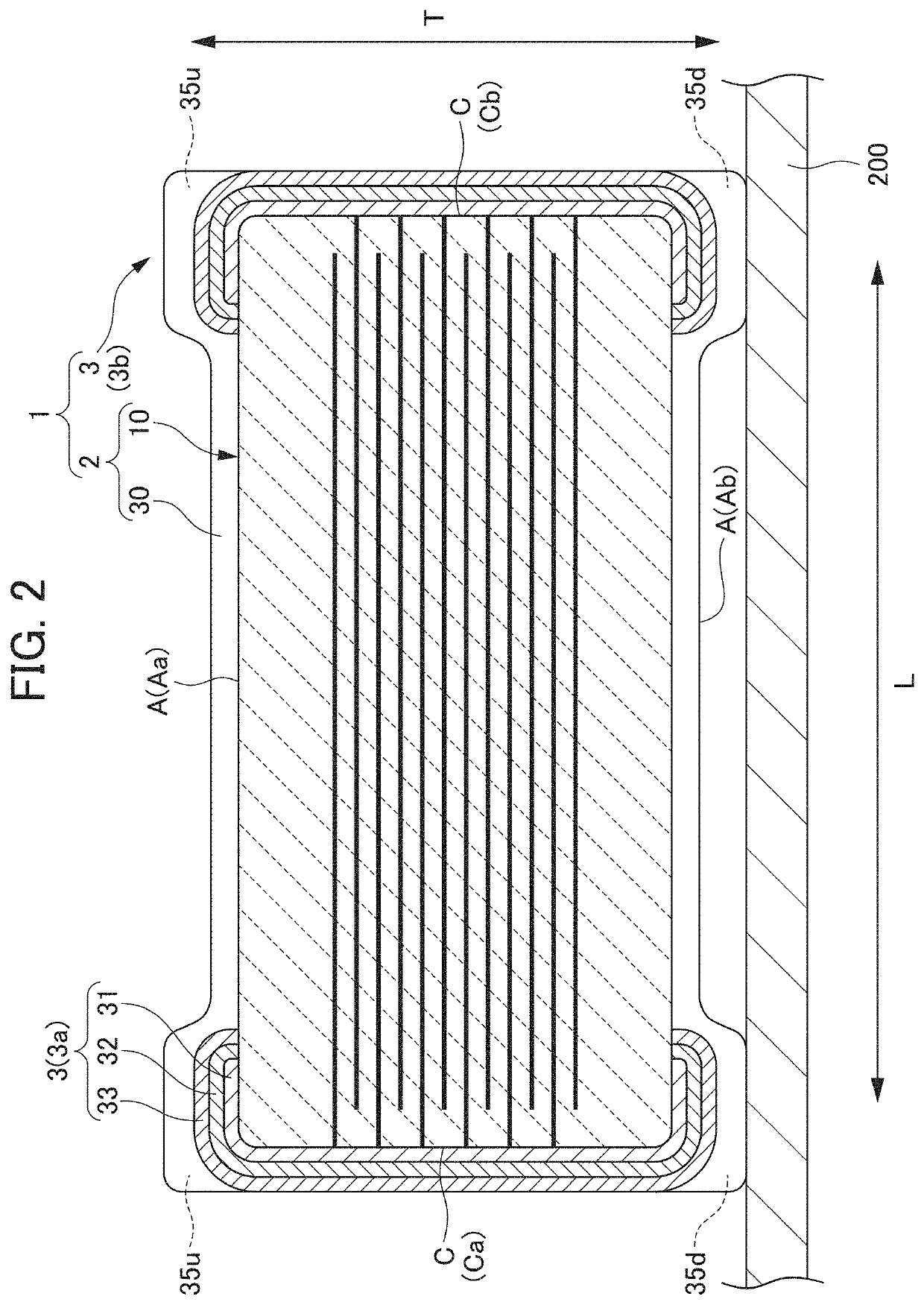
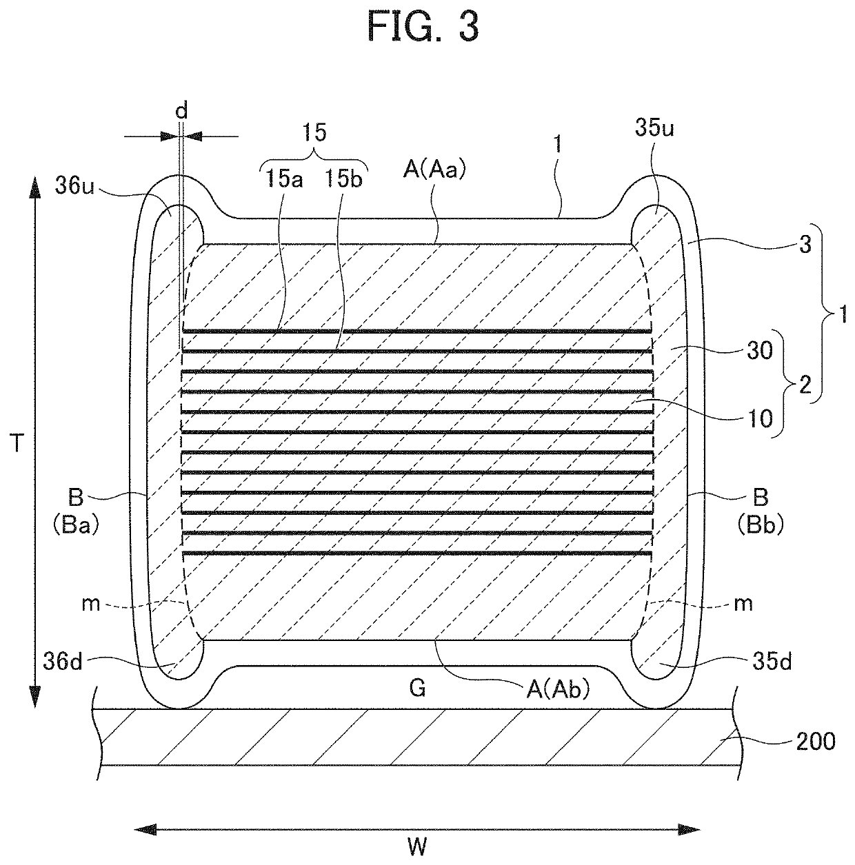
[0020]Hereinafter, multilayer ceramic capacitors according to preferred embodiments of the present invention will be described. FIG. 1 is a schematic perspective view of a multilayer ceramic capacitor 1 according to a preferred embodiment of the present invention, showing a state mounted on a substrate 200. FIG. 2 is a cross-sectional view taken along the line II-II of the multilayer ceramic capacitor 1 in FIG. 1. FIG. 3 is a cross-sectional view taken along the line III-III of the multilayer ceramic capacitor 1 in FIG. 1.

[0021]The multilayer ceramic capacitor 1 has a rectangular or substantially rectangular shape, and includes a multilayer body 2 and a pair of external electrodes 3 provided at both ends of the multilayer body 2. The multilayer body 2 includes an inner layer portion 11 including a plurality of sets of a dielectric layer 14 and an internal electrode layer 15.

[0022]In the following description, as a term representing the orientation of the multilayer ceramic capacitor...


PUM

PropertyMeasurementUnit
Lengthaaaaaaaaaa
Lengthaaaaaaaaaa
Lengthaaaaaaaaaa

Abstract

A multilayer ceramic capacitor includes a multilayer body, and two external electrodes. The multilayer body includes a multilayer body main portion including an inner layer portion including dielectric layers and internal electrode layers that are stacked, and two outer layer portions on opposite sides of the inner layer portion in a stacking direction, two side gap portions on opposite sides of the multilayer main body in a width direction, two main surfaces on opposite sides in the stacking direction, two side surfaces on opposite sides in the width direction, and two end surfaces on opposite sides in a length direction. Each of the two external electrodes are at an end surface of the multilayer body, and extend from the end surface to a portion of the main surface. An end of the side gap portion on a side of the main surface protrudes farther than the multilayer main body.

Description

CROSS REFERENCE TO RELATED APPLICATIONS[0001]This application claims the benefit of priority to Japanese Patent Application No. 2020-075811 filed on Apr. 22, 2020. The entire contents of this application are hereby incorporated herein by reference.BACKGROUND OF THE INVENTION1. Field of the Invention[0002]The present invention relates to a multilayer ceramic capacitor.2. Description of the Related Art[0003]Recently, a large-capacitance and small-size multilayer ceramic capacitor has been demanded. Such a multilayer ceramic capacitor includes an inner layer portion in which dielectric layers made of a ferroelectric material having a relatively high dielectric constant and internal electrodes are alternately stacked. Furthermore, dielectric layers of outer layer portions are provided on the upper and lower portions of the inner layer portion alternately stacked, thus forming a rectangular multilayer body. Furthermore, side gap portions are provided on both side surfaces of the rectangu...

Claims


Application Information

Patent Timeline
IPC IPC(8): H01G4/30H01G4/012H01G4/12H01G4/008H01G2/02
CPCH01G4/30H01G4/012H01G2/02H01G4/008H01G4/1218H01G4/224H01G4/12H01G4/005H01G2/065H01G4/232H01G4/1209
Inventor IKEDA, MITSURU
Owner MURATA MFG CO LTD
Learn More