Spin current magnetization rotational element, magnetoresistance effect element, magnetic memory, and high-frequency magnetic element

a technology of spin current magnetization and rotational elements, which is applied in the direction of magnetization rotational elements, instruments, and substrates/intermediate layers, etc., can solve the problems of deterioration in degree of integration of integrated circuits, and high rotational current density required to cause magnetization rotation, so as to achieve the effect of not causing deterioration in degree of integration and not increasing the consumption of electricity

Active Publication Date: 2019-03-07
TDK CORPARATION
View PDF5 Cites 9 Cited by
  • Summary
  • Abstract
  • Description
  • Claims
  • Application Information

AI Technical Summary

Benefits of technology

[0012]The present disclosure has been made in consideration of the foregoing problems, and an object thereof is to provide a spin current magnetization rotational element which is configured to be able to induce a magnetization rotation without causing an increase in consumption of electricity and a spin current magnetization rotational element which does not cause deterioration in degree of integration.
[0013]In addition, another object of the present disclosure is to provide a magnetoresistance effect element including this excellent spin current magnetization rotational element, a magnetic memory, and a high-frequency magnetic element.
[0030]According to the spin current magnetization rotational element of the aspect described above, it is possible to provide a spin current magnetization rotational element which can perform a magnetization rotation without increasing consumption of electricity and in which deterioration in degree of integration is not caused. In addition, it is possible to provide a magnetoresistance effect element including such an excellent spin current magnetization rotational element, a magnetic memory, and a high-frequency magnetic element.

Problems solved by technology

However, it has been reported that the rotational current density required to cause a magnetization rotation is high.
A generation source for an external magnetic field provided separately outside leads to deterioration in degree of integration of an integrated circuit including a spin current magnetization rotational element.
94 has a problem in that it is difficult to control the oxygen content.
Particularly, in each of elements manufactured in a thin-film process, it is difficult to form oxygen content gradients similar to each other for the elements in mass production.
A rotation of an unintended magnetization becomes noise in data and hinders long-term storage of data.
However, when a structure assisting a magnetization rotation by utilizing a wiring is employed, there is problem that more electricity is consumed due to the wiring and the degree of integration of a circuit deteriorates in order to form the wiring.

Method used


Image

  • Spin current magnetization rotational element, magnetoresistance effect element, magnetic memory, and high-frequency magnetic element
  • Spin current magnetization rotational element, magnetoresistance effect element, magnetic memory, and high-frequency magnetic element
  • Spin current magnetization rotational element, magnetoresistance effect element, magnetic memory, and high-frequency magnetic element

Examples


first embodiment

[0045]FIG. 1 is a perspective view schematically illustrating a spin current magnetization rotational element according to a first embodiment.

[0046]A spin current magnetization rotational element 10 according to the first embodiment has a first ferromagnetic layer 1, a spin-orbit torque wiring 2, and a first perpendicular magnetic field applying layer 3. In the form of FIG. 1, the first ferromagnetic layer 1 having a rectangular shape in a plan view and having the same width as the spin-orbit torque wiring 2 is laminated on a middle part on an upper surface of the belt-shaped spin-orbit torque wiring 2. The first perpendicular magnetic field applying layer 3 is formed via an insulating layer 4 on a middle side on a lower surface of the spin-orbit torque wiring 2. In addition, electrode layers 5 are formed at both end parts on the upper surface of the spin-orbit torque wiring 2. In the form of FIG. 1, the first perpendicular magnetic field applying layer 3 is formed to have a width a...

second embodiment

[0091]

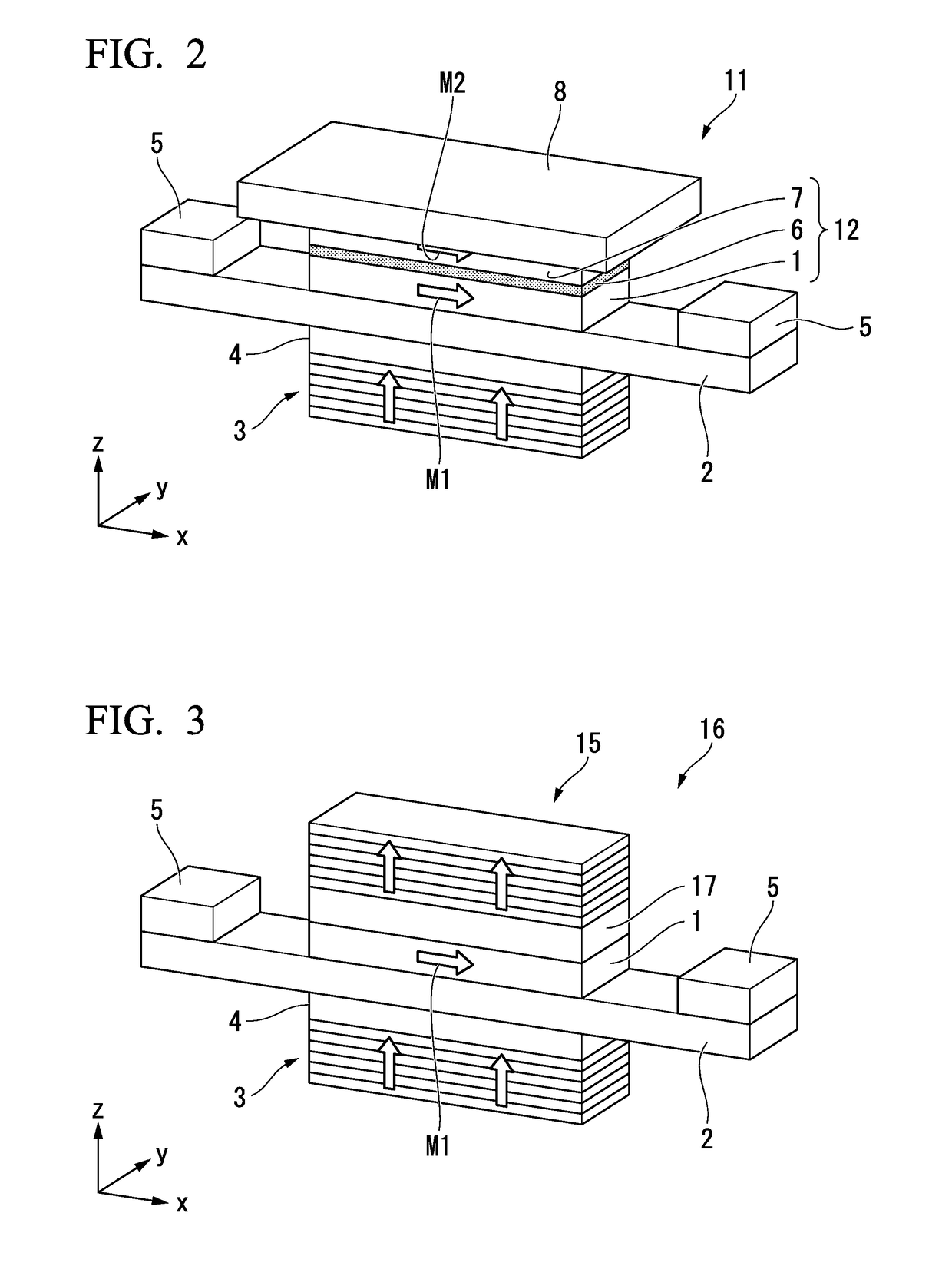
[0092]FIG. 2 illustrates a second embodiment configuring a magnetoresistance effect element 11 by using the spin current magnetization rotational element 10 of the first embodiment. The magnetoresistance effect element 11 includes a nonmagnetic layer 6 which is laminated above (z-direction) the first ferromagnetic layer 1, and a second ferromagnetic layer 7 which is laminated above (z-direction) the nonmagnetic layer 6. An electrode layer 8 is provided above the second ferromagnetic layer 7. Other configurations are equal to those of the spin current magnetization rotational element 10 of the first embodiment. The magnetoresistance effect element 11 has the first ferromagnetic layer 1, the spin-orbit torque wiring 2, the first perpendicular magnetic field applying layer 3, the insulating layer 4, and the electrode layers 5. In the magnetoresistance effect element 11, a magnetoresistance effect element core unit 12 is constituted of a laminated body including the first ferromag...

third embodiment

[0108]FIG. 3 illustrates a spin current magnetization rotational element 16 of a third embodiment having a configuration in which a second perpendicular magnetic field applying layer 15 is provided in the spin current magnetization rotational element 10 according to the first embodiment and a perpendicular magnetic field applied to the first ferromagnetic layer 1 is uniformized.

[0109]The structure of the third embodiment is characterized in that the second perpendicular magnetic field applying layer 15 is provided above (z-direction) the first ferromagnetic layer 1 via an insulating layer 17.

[0110]Other portions in the structure are equal to those in the structure of the first embodiment. The spin current magnetization rotational element 16 has the first ferromagnetic layer 1, the spin-orbit torque wiring 2, the first perpendicular magnetic field applying layer 3, the insulating layer 4, and the electrode layers 5.

[0111]The second perpendicular magnetic field applying layer 15 is co...


PUM

PropertyMeasurementUnit
atomic numberaaaaaaaaaa
spin diffusion lengthaaaaaaaaaa

Abstract

Provided is a spin current magnetization rotational element including: a spin-orbit torque wiring that extends in a first direction and is configured to generate a spin current; a first ferromagnetic layer that is laminated in a second direction intersecting the spin-orbit torque wiring and is configured for magnetization direction to be changed; and a first perpendicular magnetic field applying layer that is disposed to be separated from the spin-orbit torque wiring and the first ferromagnetic layer, the first perpendicular magnetic field applying layer being configured to apply an assistant magnetic field assisting a magnetization rotation of the first ferromagnetic layer.

Description

BACKGROUND[0001]The present disclosure relates to a spin current magnetization rotational element, a magnetoresistance effect element, a magnetic memory, and a high-frequency magnetic element.[0002]Priority is claimed on Japanese Patent Application No. 2017-170368, filed on Sep. 5, 2017, the content of which is incorporated herein by reference.DESCRIPTION OF RELATED ART[0003]A giant magnetoresistance (GMR) element constituted of a multilayer film having a ferromagnetic layer and a nonmagnetic layer, and a tunneling magnetoresistance (TMR) element using an insulating layer (tunnel barrier layer, barrier layer) as a nonmagnetic layer are known as a magnetoresistance effect element. Generally, the element resistance of a TMR element is higher than that of a GMR element, but it is advantageous that the magnetoresistance (MR) ratio thereof be higher than that of a GMR element. Therefore, a TMR element has attracted attention as an element for a magnetic sensor, a high-frequency component...

Claims


Application Information

Patent Timeline
Patent Type & Authority Applications(United States)
IPC IPC(8): H01F10/32G11C11/16H03H11/04H01L43/02
CPCH01F10/329H01F10/3286G11C11/161H03H11/04H01L43/02H01F10/3254H01L43/10G11C11/1675H03H2/00H10N50/80H10N50/10H10B61/00H10N52/00H10N50/85
Inventor SASAKI, TOMOYUKIISHITANI, YUGOSUDA, KEITA
Owner TDK CORPARATION
Why Eureka
Try Eureka