Multi-Layer Electrically Conductive Sensor

a multi-layer, electrically conductive technology, applied in the direction of measuring devices, instruments, measuring apparatus housings, etc., can solve the problems of difficult to find a metal suitable for use at higher temperatures, the operating temperature of active braze alloys is limited to about 800° c, etc., to achieve the effect of minimising stresses

Active Publication Date: 2019-02-21
FUTURE TECH SENSORS
View PDF1 Cites 1 Cited by
  • Summary
  • Abstract
  • Description
  • Claims
  • Application Information

AI Technical Summary

Benefits of technology

[0018]Each bridge can be made of any suitable electrically conductive material, e.g., a metal, and in particular a nickel-chromium-based alloy such Inconel® 600 or 625 or Haynes® 230 which are typically resistant to oxidation and maintain structural integrity at high operating temperatures. It will be understood that each bridge is not bonded or otherwise physically secured to the respective interface layer but is only in pressure contact with it. The compression force applied between each bridge and the respective interface layer will typically be sufficient such that the asperities or slight projections on adjoining surfaces experience plastic deformation, thereby increasing the contact area as required to reduce electrical contact resistance between the components.
[0042]The bridges and interface layers are as described generally above. SiC-based coatings (preferably applied using a CVD process) can be particularly advantageous if the ceramic material for the core layer is SiC and the ceramic material for the insulating layer(s) of the sensor body is SiN or SiAlON because there is a common base material, namely silicon, and the materials bond readily together during the coating process to form a robust electrically conductive layer that provides a hermetic seal at the rear face of the sensor body such that gas (e.g. air) is excluded from all internal interfaces. SiC-based coatings and silicon-based ceramic materials also have very similar CTE characteristics that minimises stresses at the interface between the two materials.

Problems solved by technology

One problem with the use of low expansion alloys is that they tend to oxidise at temperatures approaching 500° C. This places an upper limit on the operating temperature of the sensor assembly.
It can be difficult to find a metal that is suitable for use at higher temperatures and which also has a thermal expansion coefficient that is substantially similar to that of the bush and / or the sensor body.
In practice, however, the operating temperature of active braze alloys is limited to about 800° C. which is still not sufficiently high for certain operations.
Further problems are known to exist in situations where large relative movements occur between the component parts of the sensor assembly as a result of thermal expansion.
Large relative movement can only be accommodated by increasing the thickness of the compliant coatings and this can place practical limitations on the design of the sensor assembly.
One problem with these conventional sensors is that they typically utilise an alternating combination of metal and ceramic materials.
This often results in stress fractures forming in the ceramic spacers or layers, which reduce their electrical performance and may even result in the disintegration or de-lamination of the ceramic components.
Not only does this cause the sensor assembly to fail electrically, but the disintegration or de-lamination of the ceramic components also allows the metal components to vibrate and this can result in the mechanical failure of the complete sensor assembly.
A similar problem can occur if electrically conductive ceramics are used since just a small difference in the respective coefficients of thermal expansion (CTE) can be significant over the expected lifetime of the sensor assembly.
Although conventional sensors have been successfully used at high operating temperatures for short periods of time, it is unlikely that they will ever be able to meet the required operating lifetime because of the inherent weakness of the sensor assembly caused by the different thermal expansion properties of the metal and ceramic (or ceramic and ceramic) components.
Conventional sensor assemblies are also susceptible to moisture penetration which can reduce the performance of the sensor.
But such brazed layers formed when ceramic and metal components are brazed together can, in some circumstances, restrict operating lifetime and temperature due to the difference in CTE.
This can sometimes cause failure of the brazed layer after repeated thermal cycles.

Method used


Image

  • Multi-Layer Electrically Conductive Sensor
  • Multi-Layer Electrically Conductive Sensor
  • Multi-Layer Electrically Conductive Sensor

Examples


Embodiment Construction

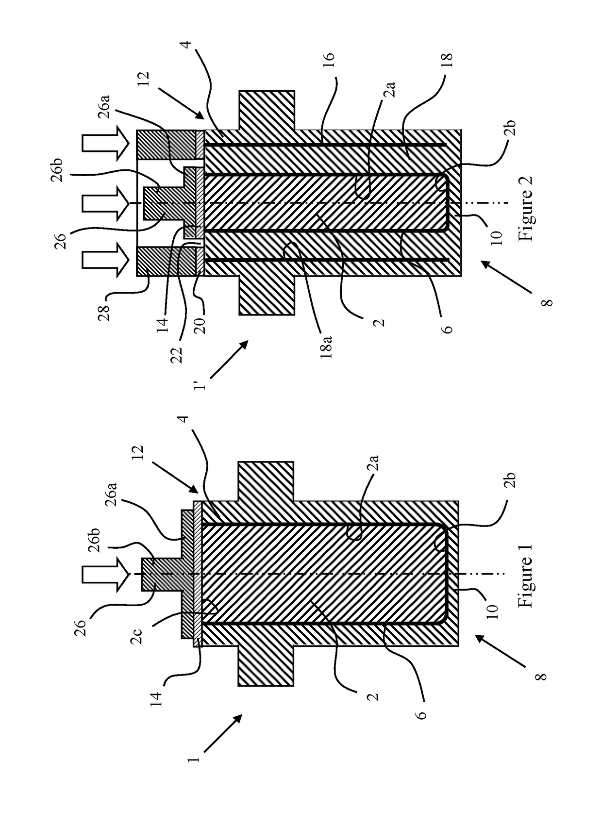
[0062]FIG. 1 shows a first coaxial sensor assembly according to the present invention. A coaxial sensor body 1 includes a core layer 2 and an outer insulating layer 4 that are made of the same electrically non-conductive ceramic material such as silicon nitride (SiN) or SiAlON. An electrode layer 6 of metal such as titanium (Ti) or molybdenum (Mo), an alloy of titanium, or an electrically conductive ceramic such as titanium nitride (TiN) or molybdenum disilicide (MoSi2) is applied as a coating and covers the cylindrical outer surface 2a of the core layer 2 (or the cylindrical inner surface of the outer insulating layer 4). The electrode layer 6 covers the front planar surface 2b and optionally the rear planar surface 2c of the core layer 2.

[0063]The outer insulating layer 4 extends along a front part 8 of the sensor body 1 which in use is exposed directly to high operating temperatures. For example, if the sensor assembly forms part of a capacitive sensor that is used to measure the...


PUM


Abstract

A sensor assembly includes an electrically conductive electrode bridge (26) and a multi-layer, integral sensor body (1). The sensor body (1) includes a core layer (2), an outer insulating layer (4) that substantially surrounds the core layer (2), and an electrically conductive electrode layer (6) between the core layer (2) and the outer insulating layer (4). The sensor body (1) also includes an electrically conductive electrode interface layer (14) at a rear part (12) of the sensor body (1) and in electrical contact with the electrode layer (6). The electrode bridge (26) is held in compression electrical contact with the electrode interface layer (14) during use.

Description

TECHNICAL FIELD[0001]The present invention relates to sensor assemblies, and in particular to sensor assemblies that incorporate a ceramic sensor body and that can be used in high temperature operating environments.BACKGROUND ART[0002]Known sensor assemblies typically comprise composite ceramic / metal components that are brazed together using a conventional brazing process. Such a known sensor assembly might include a metal housing with a metallised aluminium oxide bush brazed into the inner diameter of the housing. A sensor body is then brazed into the internal diameter of the bush.[0003]The sensor body can be made of one or more layers of metal, electrically conductive ceramic, electrically non-conductive ceramic that is made conductive by having a layer of conductive material (e.g., a metal) deposited on its surface, or a conductive ceramic / metal composite, for example. Conductive layers can define electrodes or other sensing elements or shield layers. Non-conductive layers can de...

Claims


Application Information

Patent Timeline
Patent Type & Authority Applications(United States)
IPC IPC(8): G01D11/24G01D5/16
CPCG01D11/245G01D5/16G01D11/24G01B7/14
Inventor ELLIOTT, HOWARD
Owner FUTURE TECH SENSORS
Why Eureka
Try Eureka