Liquid cold plate heat exchanger

Inactive Publication Date: 2018-11-08
宝德华南(深圳)热能系统有限公司
View PDF10 Cites 2 Cited by
  • Summary
  • Abstract
  • Description
  • Claims
  • Application Information

AI Technical Summary

Benefits of technology

This patent describes a device used to cool electronics or other heat generating devices. The device uses a liquid cold plate heat exchanger that removes heat from a heat generating device (such as a computer processor) and removes it from a cavity where it is circulated. The invention eliminates gaps between the heat sink and cap, reducing thermal resistance and improving efficiency. It also allows for relatively high heat joining operations and reduces the gap between the heat sink and cap to 0.1 mm or less. A spring plate is used to transfer heat between the cap and heat sink without the need for a direct contact between them. This eliminates the need for a separate heat transfer pad and reduces the risk of damaging the heat sink. Overall, this invention improves the thermal performance of the liquid cold plate heat exchanger.

Problems solved by technology

That is, if the heat sink top surface were to contact the cap when the cap is placed over the heat sink and the base, the heat sink may prevent the cap from being positioned properly relative to the base, e.g., in direct contact with the base.
This can cause problems, such as preventing proper brazing or other joining of the base and cap together so as to form a liquid-tight seal.
However, this gap between the heat sink and the cap can prevent effective heat transfer between the heat sink and the cap.
For example, because of the gap, heat cannot be transferred across the gap from the cap to the heat sink by conduction, but instead must transfer through the cooling fluid.
This can limit the efficiency of cooling of the heat sink or cap, e.g., if a heat generating device is thermally coupled to the cap.

Method used


Image

  • Liquid cold plate heat exchanger
  • Liquid cold plate heat exchanger
  • Liquid cold plate heat exchanger

Examples


Embodiment Construction

[0018]Aspects of the invention are not limited in application to the details of construction and the arrangement of components set forth in the following description or illustrated in the drawings. Other embodiments may be employed and aspects of the invention may be practiced or be carried out in various ways. Also, aspects and / or different features of embodiments of the invention may be used alone or in any suitable combination with each other. Thus, the phraseology and terminology used herein is for the purpose of description and should not be regarded as limiting.

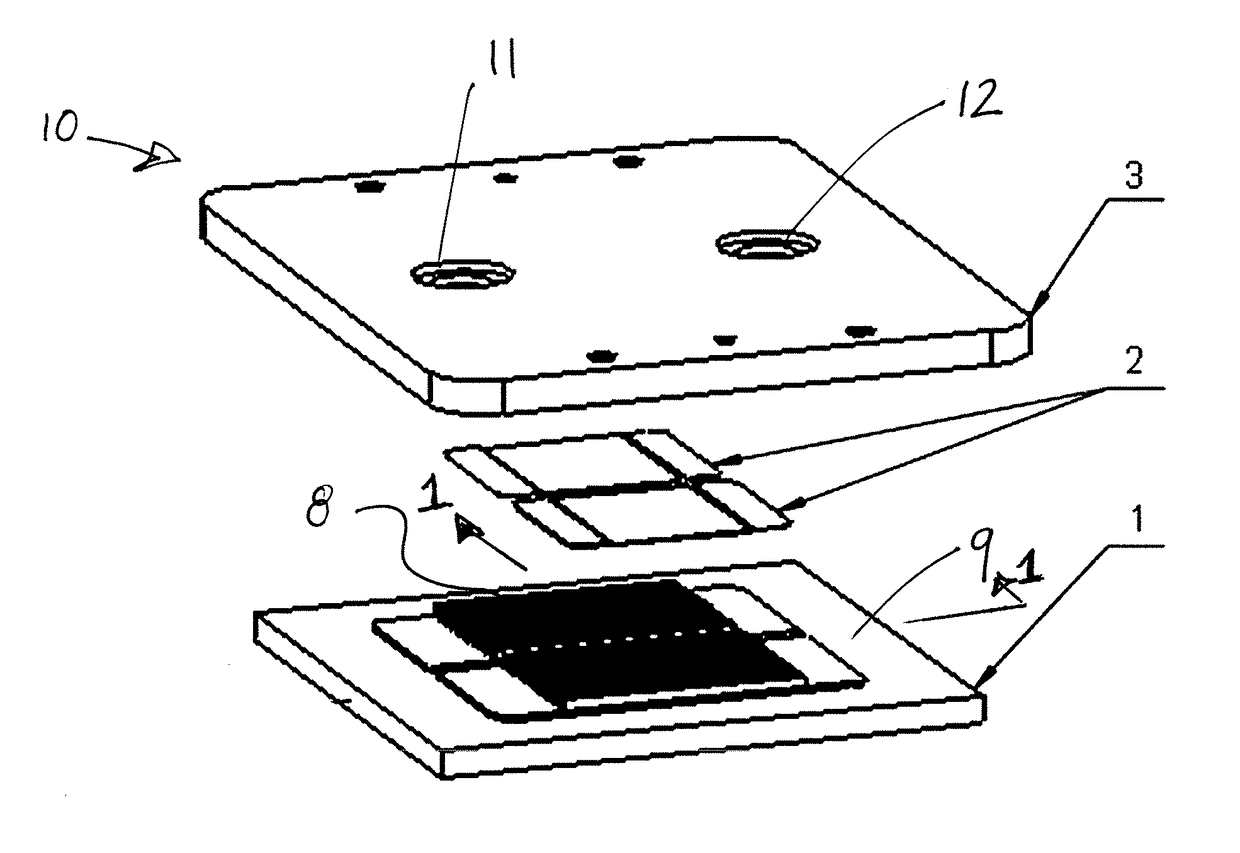
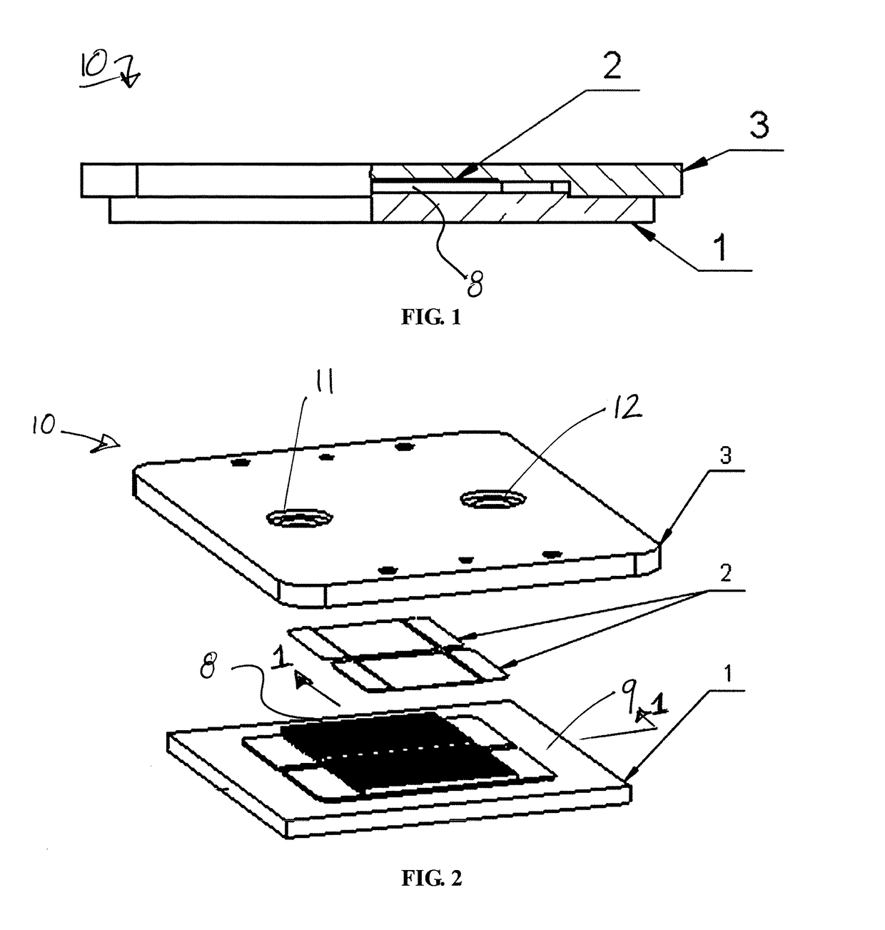
[0019]FIGS. 1 and 2 show a liquid cold plate heat exchanger 10 in an illustrative embodiment. The heat exchanger 10 includes a base 1, which may be made of a thermally conductive material such as aluminum or copper or other suitable material. Although not shown, the base 1 may be thermally coupled to a heat generating device, such as a computer processing device or other electronic component, to receive heat from the he...


PUM


Abstract

A liquid cold plate heat exchanger includes a heat sink with a plurality of fins received in a cavity between a base plate and a cap. A spring plate may be positioned between a top surface of the heat sink, e.g., over fins of the heat sink, and a lower surface of the cap in the cavity. The spring plate may at least partially and / or completely fill a gap between the heat sink and the cap, aiding in thermal conduction between the cap and heat sink.

Description

RELATED APPLICATION[0001]This Application claims priority from Chinese Application No. 201720502689.7, filed May 8, 2017, entitled “A LEAKPROOF STRUCTURE FOR HIGH TEMPERATURE VACUUM BRAZING LIQUID COLD PLATE” which is herein incorporated by reference in its entirety.FIELD OF INVENTION[0002]A liquid cold plate heat exchanger, e.g., for cooling electronics using a circulated flow of cooling fluid.BACKGROUND[0003]With the development of electronic technology, heat dissipation requirements for computer processing devices, e.g., integrated circuits or chips, has increased, requiring ever higher efficiency liquid cold plate heat exchange devices to remove the heat generated by these devices.SUMMARY OF INVENTION[0004]One type of device used to cool electronics or other heat generating devices is a liquid cold plate heat exchanger that thermally couples a heat generating device (such as a computer processor) to a heat sink that includes a plurality of fins. At least a portion of the heat si...

Claims


Application Information

Patent Timeline
IPC IPC(8): F28F9/00F28F3/12F28F3/02H01L23/473H01L23/40H01L21/48
CPCF28F9/005F28F3/12F28F3/02H01L23/473H01L23/40H01L21/4882H05K7/20254
Inventor PARAG, SONAWANEFENG, BERT
Owner 宝德华南(深圳)热能系统有限公司
Why Eureka
Try Eureka