
Data Communication

a data communication and network communication technology, applied in the field of network-based communication methods and apparatuses, can solve the problems of large playout buffer b>7/b>, overall latency, and negative impact of high pdv in many timing-critical applications, so as to reduce pdv, reduce pdv, and reduce buffering

Inactive Publication Date: 2020-10-22
TRANSPACKET
View PDF1 Cites 0 Cited by
  • Summary
  • Abstract
  • Description
  • Claims
  • Application Information

AI Technical Summary

Benefits of technology

The invention describes a method of reducing delay in transmitting information packets across a network by inserting spacer packets between them. This helps to maintain the spacing between packets and reduces the likelihood of errors. The method also allows for faster processing of the information packets by the network apparatuses. Overall, the invention improves the efficiency and reliability of information transmission in existing networks.

Problems solved by technology

A high PDV can have negative impacts in many timing-critical applications.
However, a large playout buffer 7 is undesirable as it introduces greater overall latency.
Furthermore, there can be design-dependent processes within a switch that may cause PDV depending on how the switch is implemented.
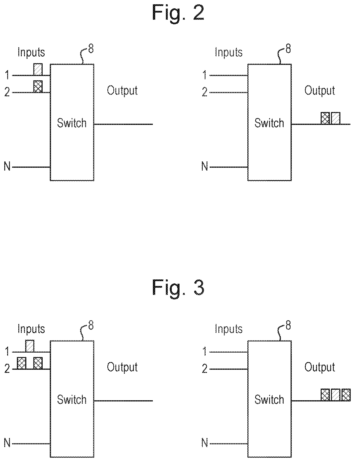
Hence delay and PDV can be affected by contention between packet streams and by mechanisms that depends on the design of network components.
A particular challenge for a network operator, when seeking to improve a network so as to reduce PDV, is that it is not typically practicable or economic to replace all the network components (bridges, switches, routers, etc.) in its existing networks.
Even if the entire network is under the operator's control, upgrading the entire network with components that introduce less PDV if often not affordable.

Method used


Image

  • Data Communication
  • Data Communication
  • Data Communication

Examples


Embodiment Construction

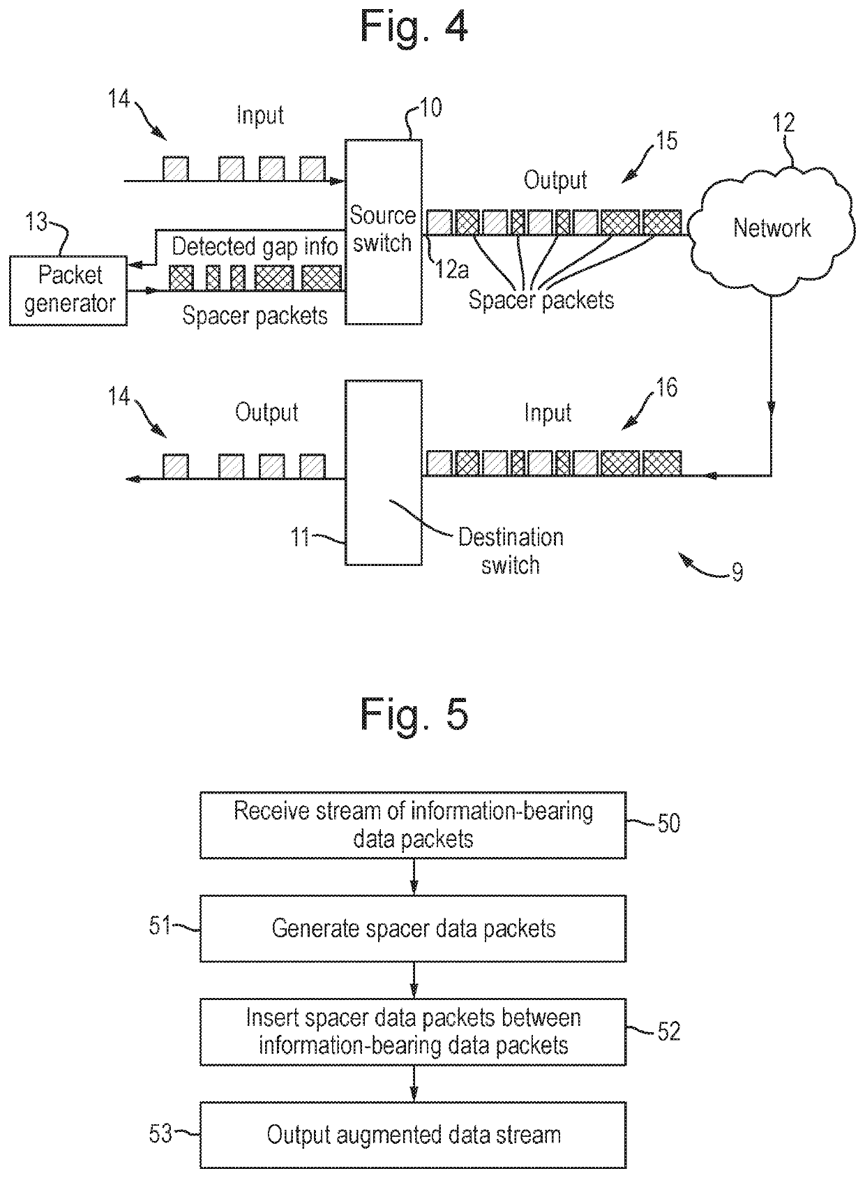
[0118]FIG. 4 shows a communication system 9 embodying the invention. It includes a source network switch 10 and a destination network switch 11 that are connected by a packet-switching network 12. The system 9 may be an asynchronous system, with each node having a respective unsynchronized clock, or it may be synchronous at the bit level. A network link 12a of the network 12 is connected to an output of the source network switch 10. The network 12 could merely be a point-to-point connection, such as a single fibre optic cable. However, more typically, the network 12 comprises multiple links, which may include any of electrical links, fibre links, microwave links, terrestrial radio links, satellite radio links, etc., and multiple intermediate switches, bridges, routers, multiplexers, demultiplexers, and / or other network components, and of which may be a potential source of packet delay variation (PDV).

[0119]It will be appreciated that the terms “source” and “destination” are used mer...


PUM


Abstract

A network-based communication system has a source network apparatus and a destination network apparatus. The source apparatus receives a stream of information-bearing packets, the stream comprising gaps between at least some of the information-bearing packets. It generates one or more spacer packets, and generates an augmented stream of packets which comprises the information-bearing packets and further comprises spacer packets located within at least some of said gaps, wherein the spacing of the information-bearing packets in the augmented stream is the same as the spacing of the corresponding information-bearing packets in the received stream. It outputs the augmented stream of packets to a network link. The destination apparatus receives the augmented stream of packets and determines whether each received packet is an information-bearing packet or a spacer packet. It outputs or processes the received information-bearing packets, or information from these packets, but discards the received spacer packets.

Description

BACKGROUND OF THE INVENTION[0001]This invention relates to network-based communication methods and apparatus.[0002]It is known to seek to lower the delay (latency) in packet switched networks-preferably, to below one millisecond. This is driven by a large range of applications including: industrial applications such as controlling robots; automotive applications such as autonomous cars; inter- and intra-datacentre communication; live television broadcast; and telecoms applications such as mobile fronthaul. The desirability of controlling the variation in the delay experienced by successive packets as they travel across a network has also been recognised. This Packet Delay Variation (PDV) is the difference between the maximum network delay and the minimum network delay. A high PDV can have negative impacts in many timing-critical applications. For example, it impacts the accuracy of the IEEE 1588 Precision Time Protocol (PTP), which is used for network synchronization. Receive-side b...

Claims


Application Information

Patent Timeline
Patent Type & Authority Applications(United States)
IPC IPC(8): H04W28/06H04L7/00H04L47/22
CPCH04L7/0012H04W28/065H04L47/22H04N21/23611H04N21/64707H04N21/64738H04N21/2221
Inventor BJORNSTAD, STEINAR
Owner TRANSPACKET
Learn More