Lighting assembly for use on a vehicle

a technology for vehicle lighting and assembly, applied in the direction of lighting and heating apparatus, planar/plate-like light guides, instruments, etc., can solve the problems of light bars manufactured, fatigue or failure, and the method of fixing

Active Publication Date: 2018-09-25
VALEO NORTH AMERICA
View PDF9 Cites 0 Cited by
  • Summary
  • Abstract
  • Description
  • Claims
  • Application Information

AI Technical Summary

Benefits of technology

[0008]Another object of the invention is to provide a light bar that is uninterrupted and continuous and that reduces or eliminates the need for small load-bearing surfaces.
[0011]Still another object is to provide a system and method of attachment that causes a light bar to be registered with respect to a light pipe which provides light to the light bar.
[0013]Still another object of the invention is to reduce or eliminate large gaps between the bezel or housing of the headlamp assembly and the light bar.
[0014]Another object is to provide an attachment system and method for a light bar and light pipe that eliminates the need for affixing the light bar to a bezel or a housing using conventional fasteners, such as screws.
[0015]Yet another object is to provide an attachment system and method that places areas where the light bar is affixed to the bezel or housing closer to its center of gravity thereby reducing or eliminating fatigue or failure risk associated with vibration.
[0016]Another object is to provide an attachment assembly for a light bar and light pipe that reduces or eliminates the need for fasteners, such as screws, to directly engage the light bar or light pipe.

Problems solved by technology

One difficulty with light bars and light pipe designs of the past is the attachment methods that were used to affix these components to the bezel or housing of the headlamp.
Normal vibration from the vehicle could sometimes cause fatigue or failure at the point where the flanges or surfaces were fixed to the bezel or housing.
The optics and the material from which the light bars were manufactured, such as Polymethyl methacrylate (PMMA) or polycarbonate (PC), also created unique problems.
For example, PMMA light bars could not be held by screws and polycarbonate light bars had a lower optical efficiency.
For those light bars that could be used with conventional fasteners or screws, the attachments were typically far away from the center of gravity (CG) of the light bar which made fatigue and failure risk high during vibration.
Another problem with light bar assemblies of the past is that they were often used with light pipes and it was often difficult to register the light bar with respect to the light pipes and / or register either the light bar or the light pipe with respect to a reflector.

Method used


Image

  • Lighting assembly for use on a vehicle
  • Lighting assembly for use on a vehicle
  • Lighting assembly for use on a vehicle

Examples


Embodiment Construction

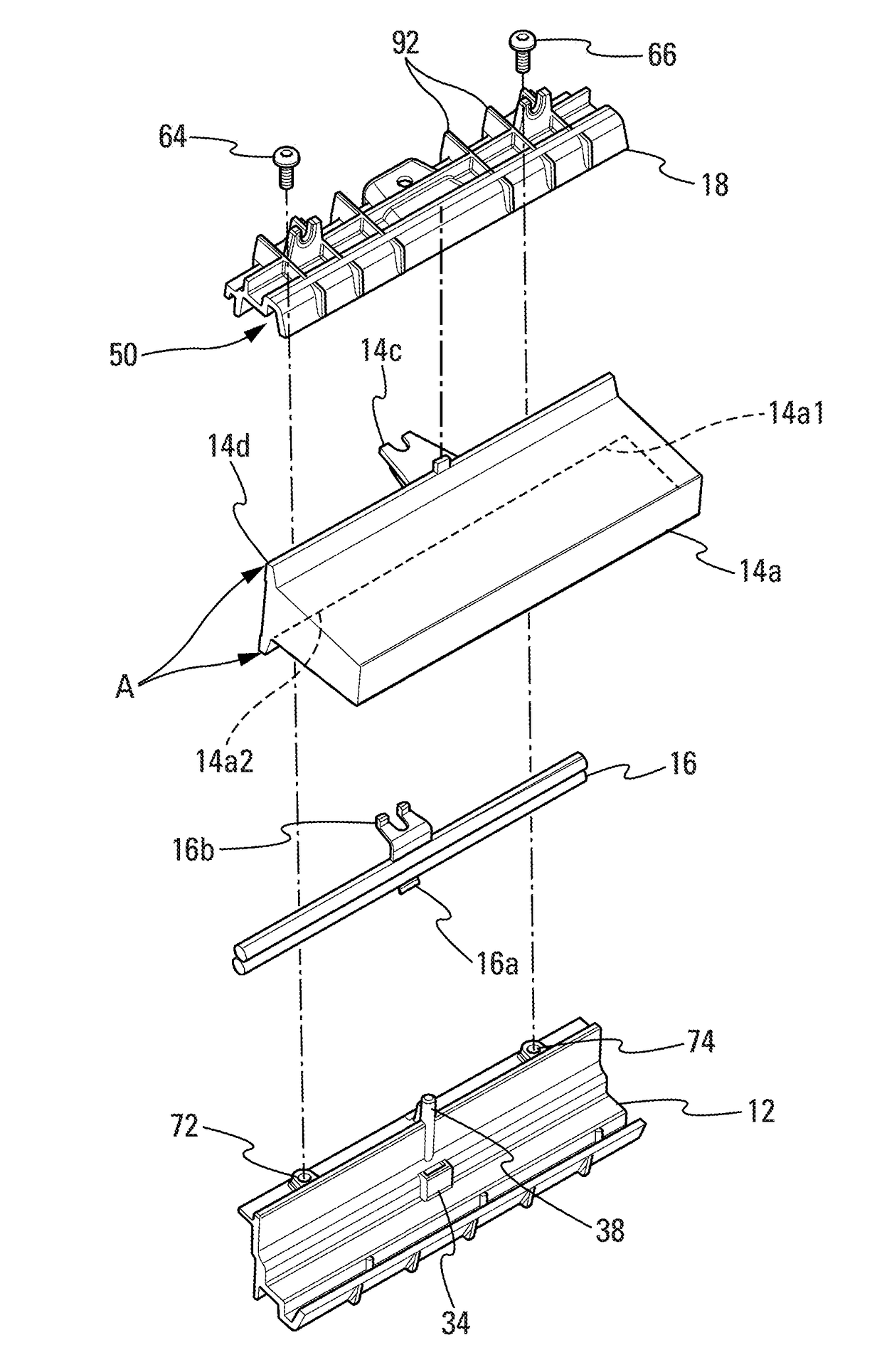
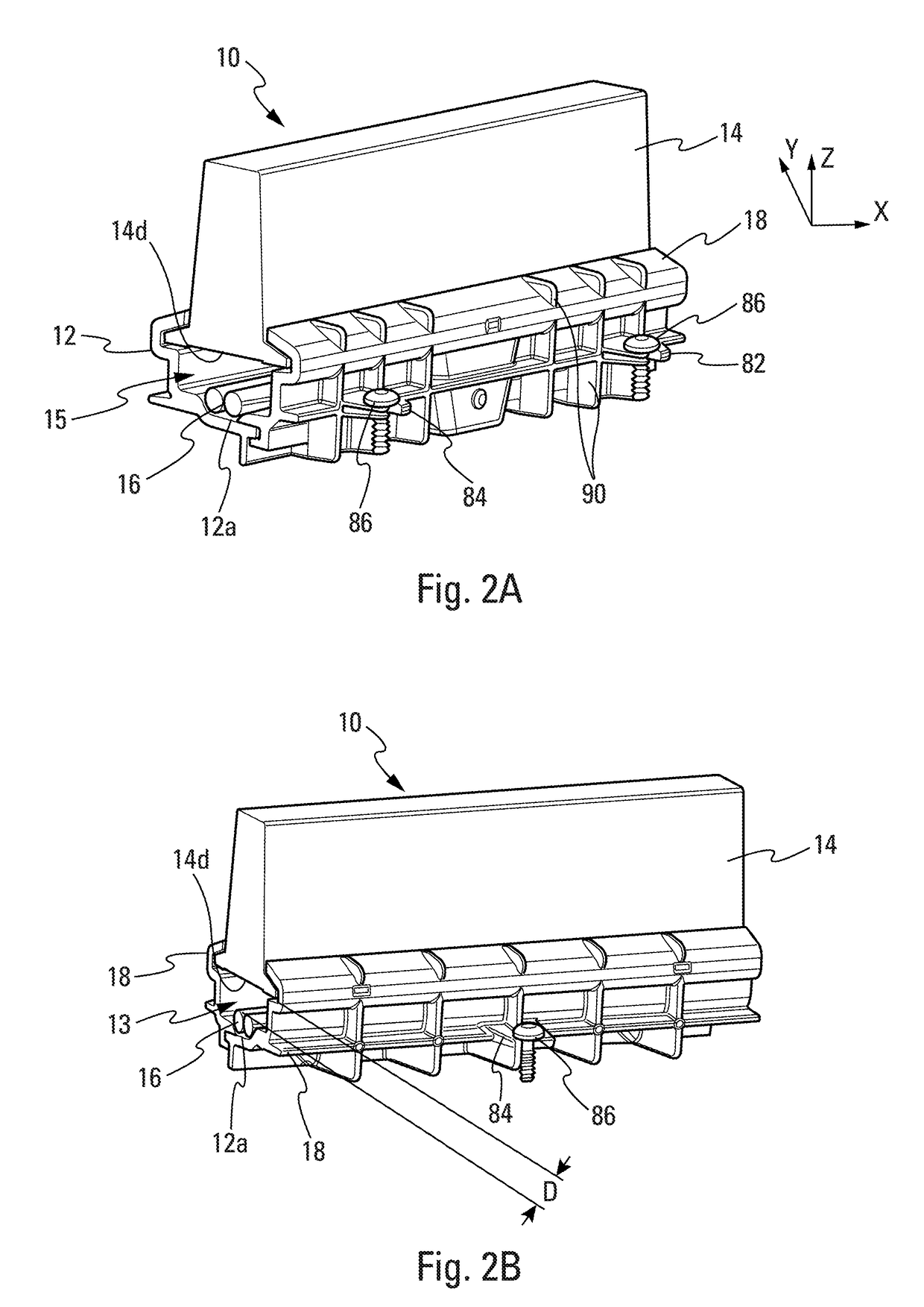
[0055]Referring now to FIGS. 1-8C, an embodiment of a lighting assembly 10 for use on a vehicle V is shown. FIGS. 2A-2B illustrate a perspective view of the assembled form of the lighting assembly 10. The lighting assembly 10 is mounted to a bezel or housing 11 of a headlamp or tail lamp assembly 13.

[0056]The lighting assembly 10 comprises a reflector 12, a light bar 14 adapted to be mounted on the reflector 12, a light pipe 16 adapted to be mounted on the reflector 12 and a bracket 18 that is also adapted to be mounted on the reflector 12 as shown. One advantageous feature of the embodiment being described is that when the bracket 18 is mounted on the reflector 12, the various components, such as the light bar 14 and light pipe 16, become captured or trapped in area 15 (FIG. 2A) by the reflector 12 and bracket 18 and these components become mounted between the reflector 12 and the bracket 18 and become automatically registered with respect to each other and with respect to the refl...


PUM


Abstract

A vehicle lighting system or assembly is shown. A lighting system or assembly comprises a reflector, a light bar for mounting on the reflector, a light pipe adapted to be mounted on the reflector and a bracket for securing to the reflector. The light pipe, the light bar and the reflector comprise locators or locating means for causing the components to become registered in a predetermined position when the components of the system are assembled.

Description

BACKGROUND OF THE INVENTION1. Field of the Invention[0001]This invention relates to a lighting assembly, and more particularly to a lighting assembly having improved light bar attachment and optical integration.2. Description of the Related Art[0002]In the field of vehicle lighting, light bars and light pipes are often used in headlamp assemblies to provide one or more lighting functions, such as headlamp lighting functions, turn signal functions, side light and / or daytime running light functions. One difficulty with light bars and light pipe designs of the past is the attachment methods that were used to affix these components to the bezel or housing of the headlamp. For example, it was not uncommon that the light bars had small load-bearing surfaces or flanges formed in the light bar at locations that were far from the center of gravity of the light bar. Normal vibration from the vehicle could sometimes cause fatigue or failure at the point where the flanges or surfaces were fixed...

Claims


Application Information

Patent Timeline
Patent Type & Authority Patents(United States)
IPC IPC(8): F21V9/00B60Q1/04F21S41/24F21V17/00F21V19/00F21S41/30F21V7/00
CPCF21S41/24B60Q1/0433F21V17/005F21V19/0035F21S41/30F21V7/005F21S43/27F21S43/239F21S43/251F21S43/31F21S43/40B60Q1/2626G02B6/0028G02B6/0031G02B6/0091
Inventor MILLER, PATRICK FRANKLIN
Owner VALEO NORTH AMERICA
Why Eureka
Try Eureka