Machinery Foundation Module

a technology of machine foundation and module, which is applied in the direction of foundation engineering, excavation, construction, etc., can solve the problems of affecting the quality of construction, so as to reduce or eliminate the need for modification

Active Publication Date: 2014-09-18
BBM RAILWAY EQUIP LLC +1
View PDF1 Cites 8 Cited by
  • Summary
  • Abstract
  • Description
  • Claims
  • Application Information

AI Technical Summary

Benefits of technology

[0013]It is therefore an object of the present invention to provide a method of installation for machinery that reduces or eliminates the need for modifications to a foundation after the foundation material is cured or set.

Problems solved by technology

A difficulty associated with minimizing gaps and rubbing is that the machinery sits in a foundation that is created using concrete forms that are often built from wooden boards and sheets.
Locating center alone is often a surveying task that can take a substantial amount of time to complete.
Again, locating the center and setting the pattern of the bolts in relation to center or another point of reference can be a lengthy and costly surveying task.
Often, a general contractor responsible for pouring concrete has difficulties achieving the tolerances required for machinery to operate correctly within a foundation.
Since the tolerance requirements are so high relative to what is often required of general contractors, locating center and bolt holes within a foundation is a time consuming and expensive process.
Additional problems with tolerances of concrete pouring may require alterations to foundations after pouring, which are time consuming and labor intensive.
Often, the first part of the foundation is poured, and then the general contractor leaves the job site because of the length of time required to install the machinery.
This requires additional costs associated with re-mobilizing the general contractor's foundation pouring operations.

Method used


Image

  • Machinery Foundation Module
  • Machinery Foundation Module
  • Machinery Foundation Module

Examples


Embodiment Construction

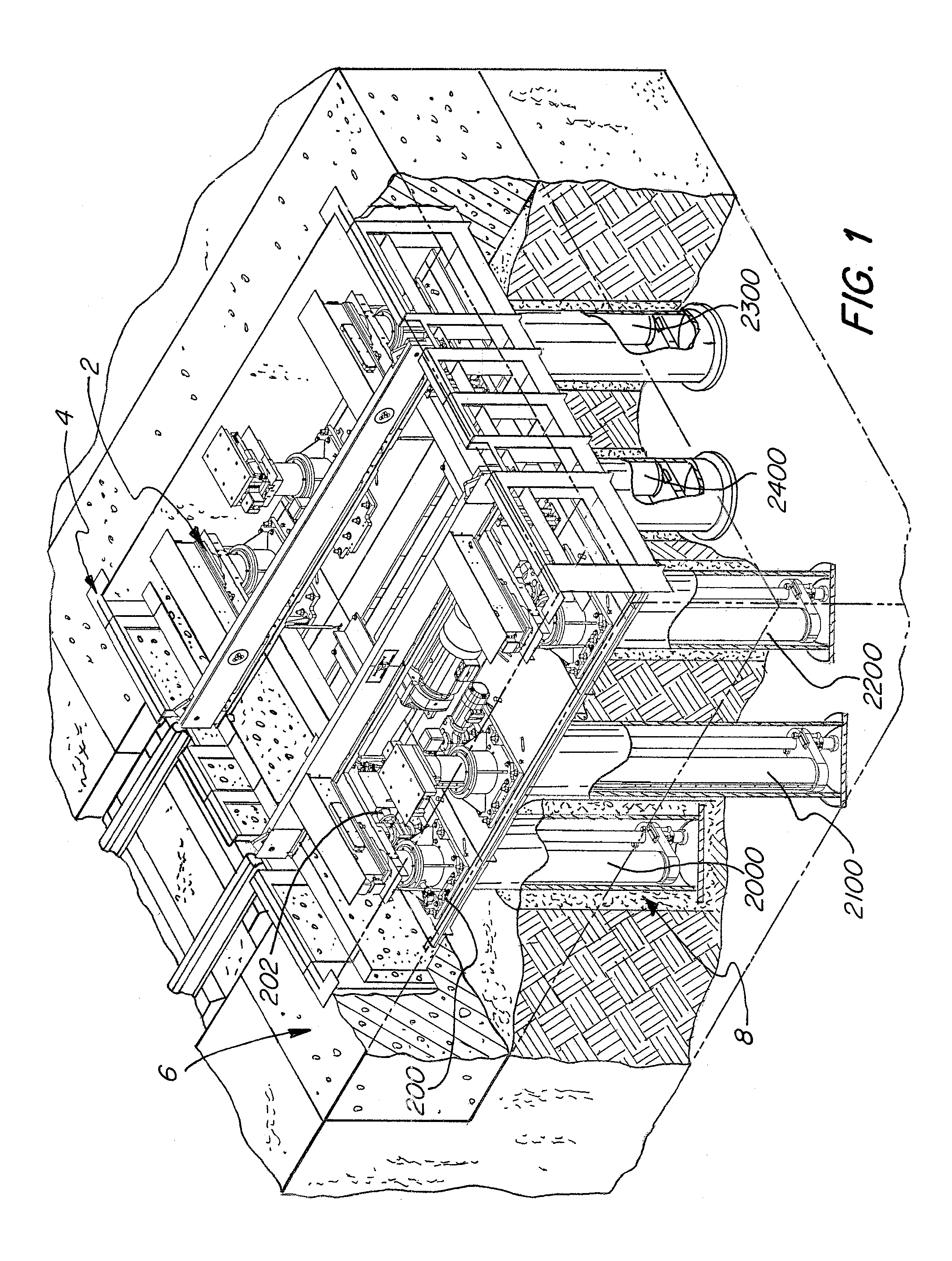
[0033]In FIG. 1, machinery 2 is installed in a foundation 6 using a frame module 4 that may be sized to receive all or part of the machinery therein. The machinery includes flanges 200 and the frame module has attachment points that allow for bolts to affix the flange to the foundation. There are multiple levels or pits 8 below the frame module 4. These pits allow for part of the machinery to extend into the pit. As shown, the machinery includes rails for receiving a rail vehicle. The wall of the foundation may have two sections as shown that define a lip. As shown, the rail supports of the machinery can rest on the lip at the bottom position in order to support the load at the ends of the rails and to provide additional resistance to deformation.

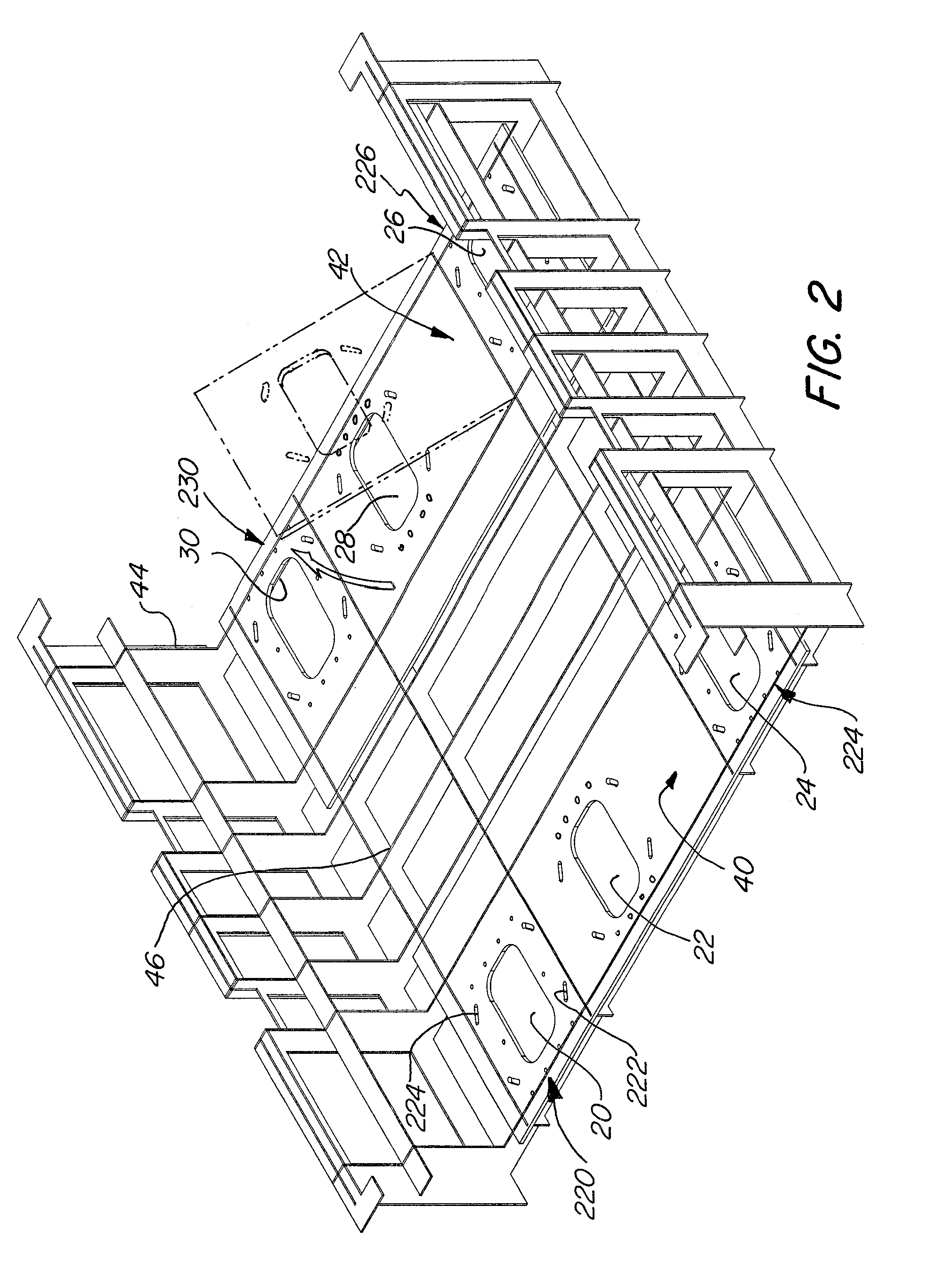
[0034]In FIG. 2, a number of attachment locations are shown, for example 220, 224, 230, 226. These attachment locations have holes arranged in a pattern around a machinery hole 20, 22, 24, 26, 28, 30 to receive bolts. The bolts receive the ...


PUM


Abstract

An assembly for supporting machinery and a method for installing the same is disclosed. A frame module including: a base with at least one attachment location, the attachment location for receiving the machinery; and a plurality of frame members affixed to the base, wherein at least one of the frame members defines a plane corresponding to a wall. A foundation has first and second sections and is disposed around the frame module. A portion of the frame module is at least partially submerged within the foundation. The machinery has at least one flange for affixing the machinery to the foundation at the attachment location. The first section of the foundation is disposed below an outside surface of the base and the second section of the foundation defines the wall of the foundation.

Description

FIELD OF THE INVENTION[0001]This invention relates to heavy lifting and positioning machinery and the manufacture thereof for installation at a site. More particularly, this invention relates to improved railway hoist machinery and an improved method of installing the same.BACKGROUND OF THE INVENTION[0002]Heavy machinery is found in many factories, rail yards, repair shops and other locations where large items are moved and positioned. For example, lifting machinery is often required to repair rail cars, engines and other railway vehicles and machinery. The lifting machinery is often made up of large support structures using hydraulic pistons, screws or large motors to move machinery. Because of the size of the lifting machinery and the size of machinery to be moved, it is often advantageous to place the lifting machinery below ground level, typically in a foundation.[0003]In the case of a rail car lifting or positioning machinery such as a repair stand or hoist, it is desirable tha...

Claims


Application Information

Patent Timeline
Patent Type & Authority Applications(United States)
IPC IPC(8): E02D27/44E02D17/02E02D15/04
CPCE02D27/44E02D17/02E02D15/04
Inventor KNAPP, RYAN W.MCGONAGLE, PETERO'DONNELL, MARK
Owner BBM RAILWAY EQUIP LLC
Why Eureka
Try Eureka