
Charge generation layer, tandem OLED device and display screen

a tandem oled device and charge generation layer technology, applied in the field of flat display, can solve the problems of long manufacturing process time and high voltage drawback and achieve the effects of reducing cost, high carrier mobility, and raising the performance of the tandem oled devi

Inactive Publication Date: 2018-11-01
WUHAN CHINA STAR OPTOELECTRONICS TECH CO LTD
View PDF5 Cites 4 Cited by
  • Summary
  • Abstract
  • Description
  • Claims
  • Application Information

AI Technical Summary

Benefits of technology

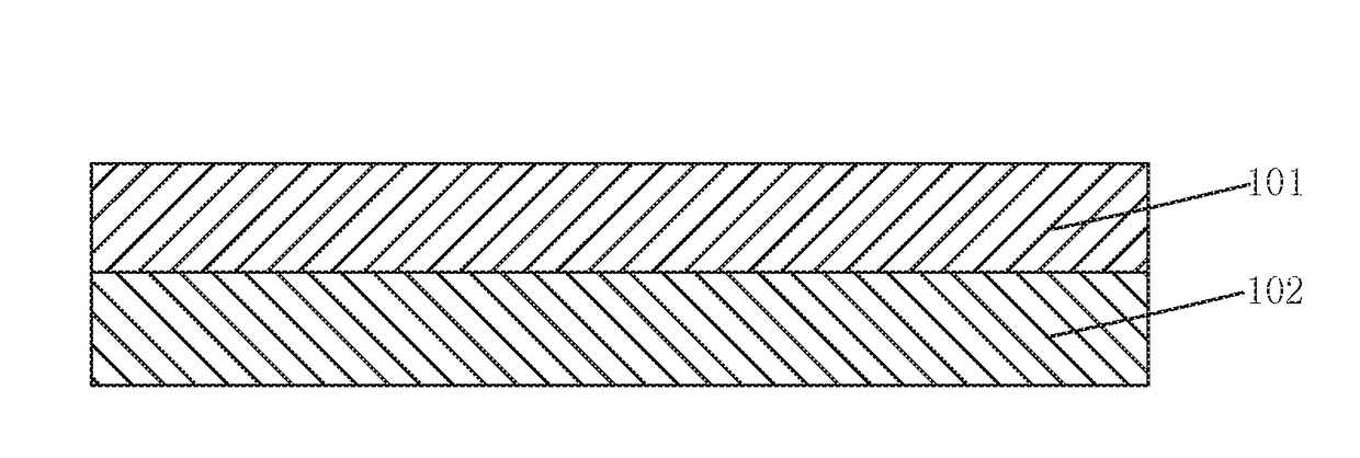
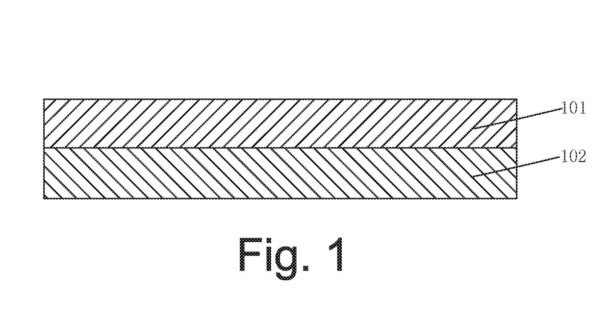
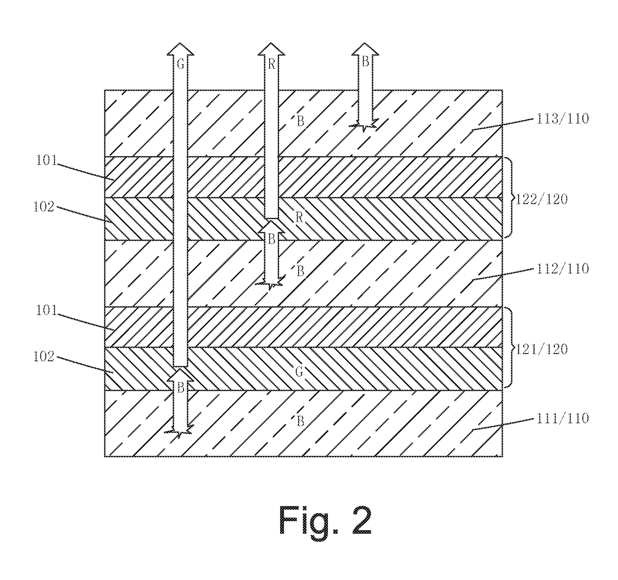
The present invention provides a charge generation layer that consists of organic-inorganic hybrid perovskite materials. This layer has high carrier mobility and can emit light under light excitation to affect light color conversion, which is beneficial for improving the performance of tandem OLED devices, reducing cost, and simplifying manufacturing process. The tandem OLED device employing this charge generation layer has improved carrier transport and effective light color conversion, leading to higher performance, lower cost, and simplified manufacturing process. The display screen using this tandem OLED device has higher performance, lower cost, and simplified manufacturing process.

Problems solved by technology

It is a significant issue how to make the charge generation layer generate carriers efficiently, transport carriers rapidly and inject carriers effectively, for achieving a high-performance tandem OLED device.
However, the tandem OLED device using the aforementioned charge generation layer still has a drawback of very high voltage.
Therefore, in the traditional tandem OLED device, charge generation layer cannot illuminate by itself, such that a lot of light-emitting units are required to illuminate and mix lights for generating white light.
However, material lifespan of various light-emitting units are different, their long-time usage would readily result in color shifts, and more light-emitting units will occupy more evaporation sources, thereby causing a longer manufacturing process time.

Method used


Image

  • Charge generation layer, tandem OLED device and display screen
  • Charge generation layer, tandem OLED device and display screen
  • Charge generation layer, tandem OLED device and display screen

Examples


Embodiment Construction

[0036]For better explaining the technical solution and the effect of the present invention, the present invention will be further described in detail with the accompanying drawings and the specific embodiments.

[0037]An organic-inorganic hybrid perovskite material has a high potential of acting as charge generation layer material in a tandem OLED device owing to its great carrier transporting capability. Besides, the organic-inorganic hybrid perovskite material has a higher optical absorption coefficient such that this property can be utilized to accomplish a function of light color conversion, and to emit a light longer than excitation light wavelength, thereby achieving an objective of light color adjustment. This can decrease a quantity of light-emitting units of the tandem OLED device, or can decrease the kinds of luminous materials in use, and shorten a manufacturing process time. In aspect of film layer preparation, the organic-inorganic hybrid perovskite material can not only ...


PUM


Abstract

The present invention provides a charge generation layer, a tandem OLED device and a display screen. The charge generation layer of the present invention consists of organic-inorganic hybrid perovskite material, a structural formula of which is ABX3, wherein A is an organic amino group, B is 4th main group metal ion or transition metal ion, X is a halogen element or a combination of a variety of halogen elements. The organic-inorganic hybrid perovskite material has not only a great carrier transporting capability but also further has a property with a higher optical absorption coefficient, and can emit a light longer than excitation light wavelength, and thus further can possess an effect on light color conversion in the tandem OLED device, thereby being beneficial to raising the performance of the tandem OLED device, lowering cost, and simplifying manufacturing process.

Description

FIELD OF THE INVENTION[0001]The present invention relates to a flat display field, and more particular to a charge generation layer, a tandem OLED device and a display screen.BACKGROUND OF THE INVENTION[0002]At the present, organic light-emitting diode (OLED) devices have been broadly applied in flat panel display and solid-state lighting etc., in various fields for daily life. Among them, OLED display technology, which is a flat panel display technology with extremely high development prospect, has greatly excellent display performances, especially in solid-state self-illumination, simplified structure, ultra thin thickness, fast response speed, wide viewing angle, low power consumption, accomplishable flexible display etc. properties, honored as ‘dreamlike display’, in addition that their production equipment investment is far less than that of liquid crystal display screen (Liquid Crystal Display, LCD), and thus is in favor with a number of large display factories, as now to be a...

Claims


Application Information

Patent Timeline
Patent Type & Authority Applications(United States)
IPC IPC(8): H01L51/52H01L51/50H01L51/56H01L27/32
CPCH01L51/52H01L51/5048H01L51/56H01L27/3209H01L2251/301H01L2251/53H10K59/38H10K50/13H10K50/19H10K85/50H10K50/80H10K50/14H10K59/32H10K71/00H10K2102/00H10K2102/302
Inventor WANG, XU
Owner WUHAN CHINA STAR OPTOELECTRONICS TECH CO LTD
Learn More