
Fingerprint detection device and driving method therefor

Active Publication Date: 2018-10-18
CRUCIALTEC
View PDF0 Cites 8 Cited by
  • Summary
  • Abstract
  • Description
  • Claims
  • Application Information

AI Technical Summary

Benefits of technology

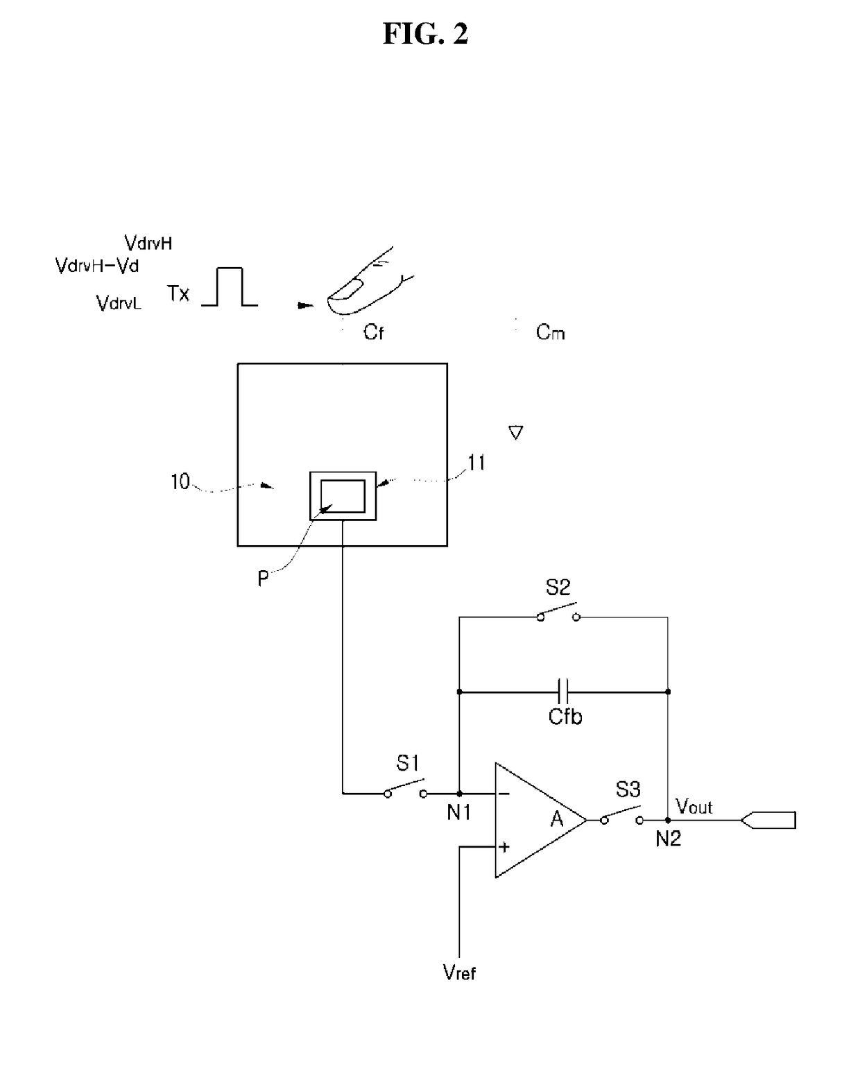
The present invention aims to prevent degraded output signals when using a fingerprint detection device on electronic devices made of metallic materials. It achieves this without the need for a charge pump to generate a driving signal, reducing design complexity and cost. Additionally, the invention maintains a consistent output signal even with parasitic capacitance components present. This eliminates the need for a charge pump and simplifies design.

Problems solved by technology

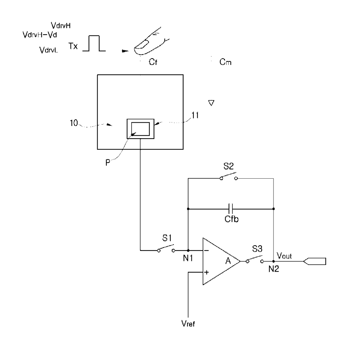
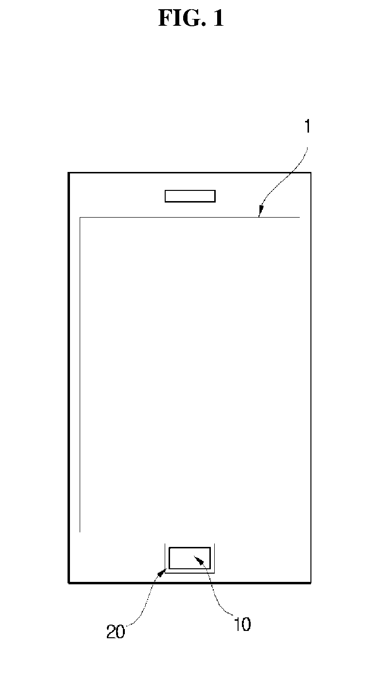
However, the fingerprint recognition device employing this method necessarily requires the external electrode 20 for applying a driving signal.
Therefore, the size and the manufacturing cost of the fingerprint recognition device increase, and the external electrode 20 limits the design of electronic device 1.

Method used


Image

  • Fingerprint detection device and driving method therefor
  • Fingerprint detection device and driving method therefor
  • Fingerprint detection device and driving method therefor

Examples


Embodiment Construction

[0061]Hereinafter, the present invention will be described with reference to the accompanying drawings. However, the present invention may be implemented in various different forms and thus is not limited to the embodiments described herein. In the drawings, parts unrelated to the description have been omitted to clearly describe the present invention, and like reference numerals indicate like elements throughout the specification.

[0062]In the specification, when a part is “connected” to another part, the parts may not only be “directly connected” to each other but may also be “indirectly connected” via an intermediate member. Also, when a part “includes” a certain component, it means that, another part may be included therein and is not excluded unless particularly defined otherwise.

[0063]Embodiments of the present invention will be described in detail below with reference to the accompanying drawings.

[0064]FIG. 4 is a diagram schematically showing a configuration of a fingerprint ...


PUM


Abstract

A fingerprint detection device including a plurality of fingerprint sensing elements, and each fingerprint sensing element includes: a sensing electrode for forming a sensing capacitance from a relationship with a subject; an amplifier having a first input end connected to the sensing electrode and a second input end into which a bias signal, of which a potential is changed from a high level to a low level or from the low level to the high level during a fingerprint detection operation, is inputted; and a gain controller including a plurality of sub-feedback capacitances, the gain controller selectively connected between the first input end and an output end of the amplifier.

Description

CROSS-REFERENCE TO RELATED APPLICATIONS[0001]This application is a National Stage Entry of International Application No. PCT / KR2016 / 005429, filed on May 23, 2016, and claims priority from and the benefit of Korean Patent Application No. 10-2015-0087815, filed on Jun. 19, 2015, and Korean Patent Application No. 10-2015-0156626, filed on Nov. 9, 2015, which are hereby incorporated by reference for all purposes as if fully set forth herein.BACKGROUNDField[0002]The present invention relates to a fingerprint detection device and an operating method of the same, and more particularly, to a fingerprint detection device in which a bias signal corresponding to a driving signal is supplied from the inside of each fingerprint sensing is element and an operating method of the same.Discussion of the Background[0003]Since people have different fingerprints, fingerprints are frequently used in the personal identification field. In particular, fingerprints are widely used as a means of personal aut...

Claims


Application Information

Patent Timeline
IPC IPC(8): G06K9/00
CPCG06K9/0002G06V40/1306
Inventor KIM, JUNG HYUNKIM, TAEK MOOKIM, DONG WOON
Owner CRUCIALTEC
Learn More