
Inspection apparatus and inspection method for membrane electrode assembly

a membrane electrode and inspection apparatus technology, applied in the direction of instruments, fuel cells, electrochemical generators, etc., can solve the problems of defective products being circulated, dielectric breakdown may not be detected, and flow through the electrolyte membrane, so as to prevent the circulation of defective products and suppress the deterioration of carbon

Active Publication Date: 2018-10-11
TOYOTA JIDOSHA KK
View PDF2 Cites 14 Cited by
  • Summary
  • Abstract
  • Description
  • Claims
  • Application Information

AI Technical Summary

Benefits of technology

The present invention relates to an inspection apparatus and method for a membrane electrode assembly used in fuel cells. The invention accurately determines if the membrane electrode assembly is defective or not by measuring the breakdown voltage and can prevent the circulation of defective products. It is also important to note that the carbon deterioration amount becomes large when the relative humidity in the inspection chamber is high. To address this issue, the inspection apparatus includes a dehumidification unit to reduce the relative humidity in the inspection chamber and conduct the breakdown voltage test under a dry atmosphere, which prevents the carbon deterioration during the test. The inspection method involves comparing the time integral value of current for the inspection time with a threshold preset based on the carbon deterioration rate to accurately identify the membrane electrode assembly with carbon deterioration. The invention prevents the circulation of defective products and ensures the quality of the membrane electrode assembly for fuel cells.

Problems solved by technology

In the breakdown voltage test, if dielectric breakdown of an electrolyte membrane occurs immediately before the application of a test termination voltage thereto, there is a possibility that a current flowing through the electrolyte membrane during the dielectric breakdown may not be detected, and in such a case, the resulting defective product may be circulated.
By the way, there is a concern that a voltage that is applied to a membrane electrode assembly during a breakdown voltage test may cause deterioration of (deterioration of carbon in) an electrode catalyst layer or a gas diffusion layer formed of a carbon material constituting the membrane electrode assembly, which in turn may degrade the performance of the membrane electrode assembly.
Therefore, it would be impossible to accurately identify the state of deterioration of the electrolyte membrane or the like after a passage of the inspection time only by measuring the amount of current flowing through the membrane electrode assembly and comparing the measured amount of current with a threshold.
It has been identified by the inventors that when the relative humidity of an inspection chamber in which the inspection apparatus is placed is high, the carbon deterioration amount also becomes large.

Method used


Image

  • Inspection apparatus and inspection method for membrane electrode assembly
  • Inspection apparatus and inspection method for membrane electrode assembly
  • Inspection apparatus and inspection method for membrane electrode assembly

Examples


embodiment 1

of Inspection Apparatus and Inspection Method for Membrane Electrode Assembly

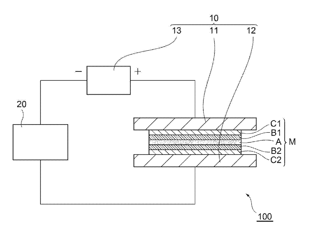
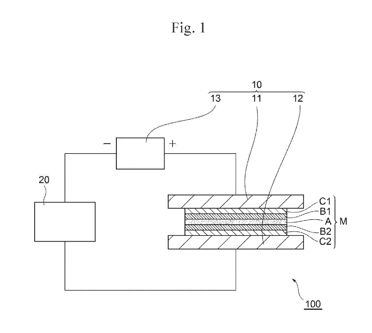
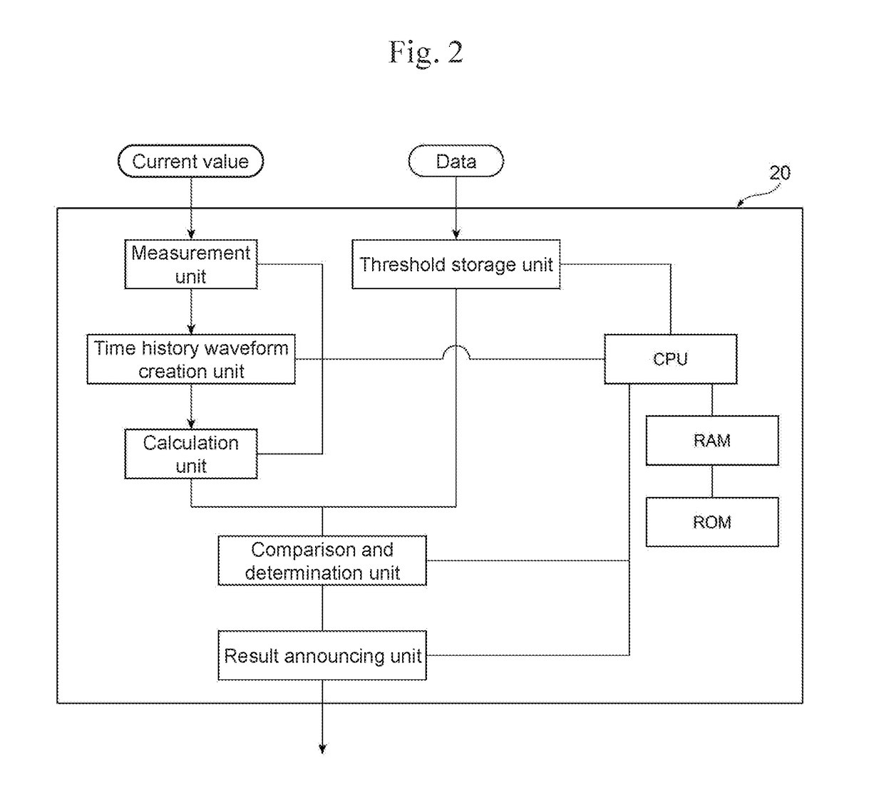
[0030]FIG. 1 is a schematic diagram of Embodiment 1 of an inspection apparatus for a membrane electrode assembly of the present disclosure. FIG. 2 is a block diagram illustrating the internal configuration of a measurement and operation determination unit. The inspection apparatus 100 shown in the drawing generally includes a voltage application unit 10 and a measurement and operation determination unit 20.

[0031]First, the configuration of a membrane electrode assembly M, which is a target to be inspected, will be described. The membrane electrode assembly M shown in FIG. 1 includes an electrolyte membrane A with ion permeability, anode-side and cathode-side electrode catalyst layers B1 and B2 sandwiching the electrolyte membrane A therebetween, and gas diffusion layers C1 and C2 on the outer sides thereof. The electrolyte membrane A is formed of, for example, a fluorine-based ion exchange membrane containi...

embodiment 2

of Inspection Apparatus and Inspection Method for Membrane Electrode Assembly

[0046]FIG. 5 is a schematic diagram of Embodiment 2 of the inspection apparatus for a membrane electrode assembly of the present disclosure. An inspection apparatus 100A shown in the drawing is an apparatus that further includes a dehumidification unit 30 in addition to the components of the inspection apparatus 100 shown in FIG. 1.

[0047]As the dehumidification unit 30, a blower, a dehumidifying agent, or the like is applicable. When a blower is applied, air is forcibly blown with the blower into an inspection chamber that houses the inspection apparatus 100A therein so as to reduce the relative humidity in the chamber, and when a dehumidifying agent is used, a plurality of dehumidifying agents are attached to the interior of the inspection chamber so as to reduce the relative humidity in the inspection chamber.

[0048]It has been identified by the inventors that when the relative humidity of the inspection c...


PUM


Abstract

Provided are an inspection apparatus and method capable of accurately detecting a defective membrane electrode assembly based on the rate of deterioration of carbon forming an electrode catalyst layer or the like of the assembly. The apparatus is an inspection apparatus for a membrane electrode assembly including an electrolyte membrane and anode-side and cathode-side electrode catalyst layers made of carbon materials to form a fuel cell, the apparatus including a voltage application unit that applies voltage to the assembly; and a measurement and operation determination unit that measures a time history waveform of current that flows upon application of the voltage for an inspection time and calculates the time integral value of current for the inspection time, and compares the time integral value of current with a threshold of the time integral value of current preset based on a predetermined carbon deterioration rate so as to determine the assembly to be defective if the time integral value of current is greater than the threshold.

Description

CROSS REFERENCE TO RELATED APPLICATIONS[0001]The present application claims priority from Japanese patent application JP 2017-076267 filed on Apr. 6, 2017, the content of which is hereby incorporated by reference into this application.BACKGROUNDTechnical Field[0002]The present disclosure relates to an inspection apparatus and an inspection method for a membrane electrode assembly to form a fuel cell.Background Art[0003]A polymer electrolyte fuel cell includes a membrane electrode assembly (MEA) that includes an electrolyte membrane with ion permeability and anode-side and cathode-side electrode catalyst layers sandwiching the electrolyte membrane therebetween. There is also another concept of a membrane electrode assembly that further includes a gas diffusion layer (GDL) for promoting a flow of gas and increasing the current-collecting efficiency on the outer side of each electrode catalyst layer. In this specification, both of such configurations are included in the types of membra...

Claims


Application Information

Patent Timeline
IPC IPC(8): G01R31/36H01M8/04664H01M8/1004H01M8/1018
CPCG01R31/3679H01M8/04664H01M8/1004H01M8/1018G01R31/3627H01M2008/1095G01R31/385G01R31/392Y02E60/50
Inventor SHINOZAKI, KAZUMA
Owner TOYOTA JIDOSHA KK
Learn More