Manual Tool Capable of Unfolding Only One Work Accessory
- Summary
- Abstract
- Description
- Claims
- Application Information
AI Technical Summary
Benefits of technology
Problems solved by technology
Method used
Image
Examples
embodiment 1 (referring to figs.11-19)
Embodiment 1 (Referring to FIGS. 11-19)
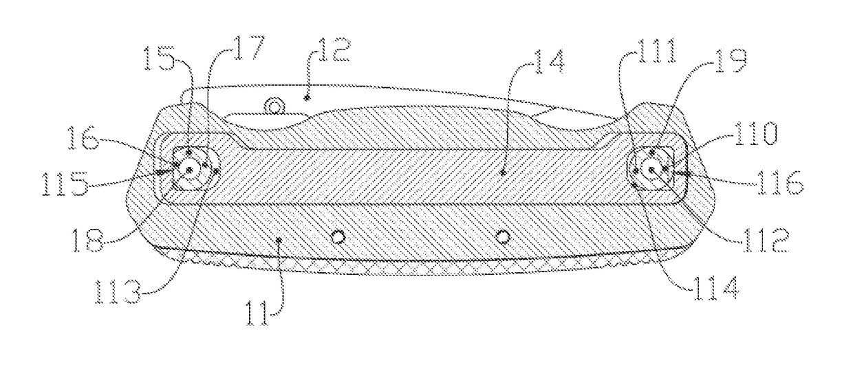
[0059]The first work accessory 12 is rotationally surrounding the first pivot 18 that is arranged on one end of the handle 11 by the first axle sleeve 15 set on the end of the first work accessory 12. The outer diameter of the first axle sleeve 15 has a small diameter part 16 and a large diameter part17. The second work accessory 13 is rotationally surrounding the second pivot 112 arranged on the other end of the handle 11 by the second axle sleeve 19 arranged on the end of the second work accessory 13w. The outer diameter of the second axle sleeve 19 has a large diameter part 110 and a small diameter part 111.
[0060]Referring to FIGS. 13, 16 and 19, the associated accessory 14 is a pull rod assembled inside the handle 11 and can move along its length. The two ends of the pull rod are surrounding the first axle sleeve 15 and the second axle sleeve 19 through the first through hole 113 and the second through hole 114 respectively. The first throu...
embodiment 2 (referring to figs.1-10)
Embodiment 2 (Referring to FIGS. 1-10)
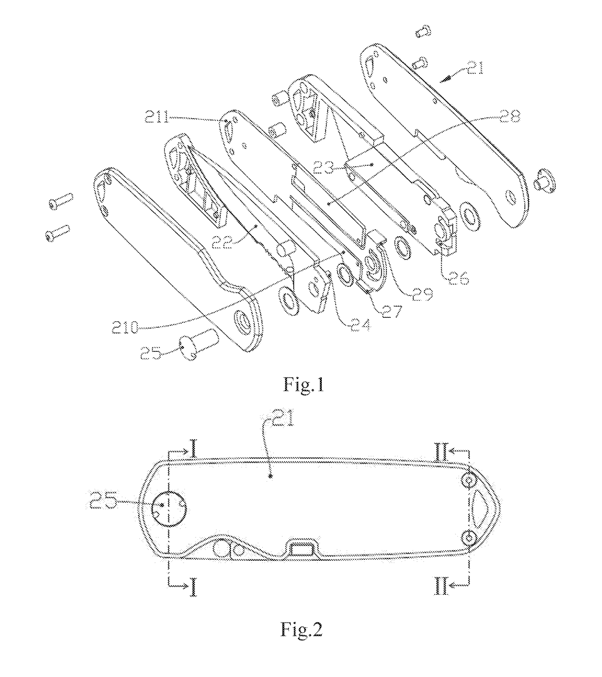
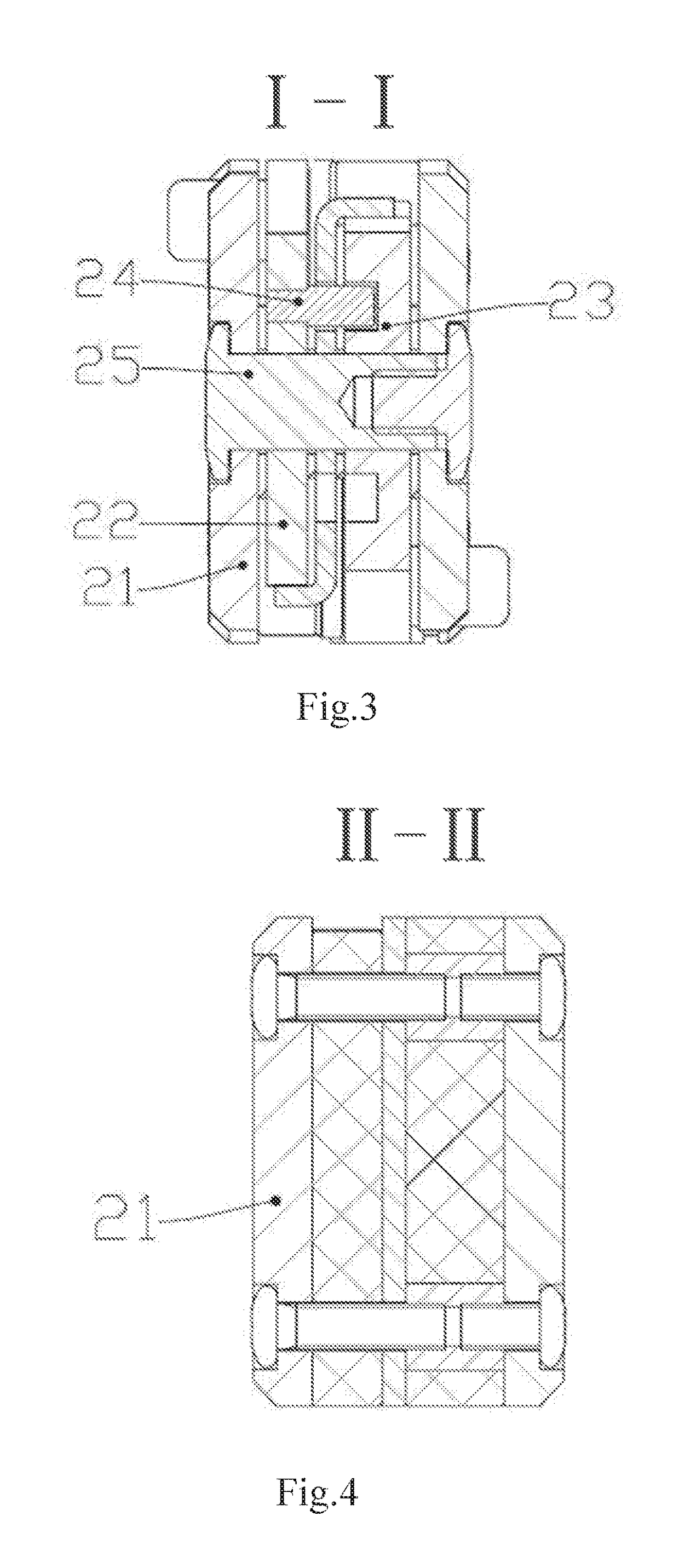
[0070]A first work accessory 22 and a second work accessory 23 are reversely arranged on the same pivot 25 of the handle 21 (being reversely set means that the unfold direction of the first work accessory and the second work accessory are opposite, as shown in FIG. 1. The first work accessory is unfolded when rotating clockwise while the second work accessory is unfolded when rotating anticlockwise).
[0071]A stroke slot 26 is set on one work accessory (a stroke slot 26 is set on the second work accessory 23 is shown in the Figure) and a pin is set on the other work accessory (a pin set on the first work accessory 22 is shown in the Figure) as the associated accessory 24, and the pin extends into the stroke slot 26 (the position of the stroke slot 26 and the pin can be exchanged in a specific embodiment).
[0072]In the folding state (as shown in FIGS. 1-6), the pin is located on one end of the stroke slot 26. Relative to the stroke slot 26, the pin ...
embodiment 3 (referring to figs.20-28)
Embodiment 3 (Referring to FIGS. 20-28)
[0078]In the embodiment, the manual tool capable of unfolding only one work accessory has a constraining state in addition to the unfolding state and the folding state. In this case, the unfolding state may comprise full unfolding and unfolding at an angle (for example, unfolding at 90 degrees, 120 degrees, 160 degrees, etc.). In the unfolding state, the first work accessory 32 or the second work accessory 33 may be used. The constraining state refers to a state between the folding state and the unfolding state, and in this state, both the first work accessory 32 and the second work accessory 33 are unfolded at an angle, but neither of the two work accessories can be used; when one of the first work accessory 32 and the second work accessory 33 continues opening to the unfolding state, the other should first return to the folding state.
[0079]As shown in FIGS. 20, 21, 24 and 25, a through hole 321 is provided on the end of the first work accesso...
PUM
 Abstract
Description
Claims
Application Information
 - R&D
- Intellectual Property
- Life Sciences
- Materials
- Tech Scout
- Unparalleled Data Quality
- Higher Quality Content
- 60% Fewer Hallucinations
Browse by: Latest US Patents, China's latest patents, Technical Efficacy Thesaurus, Application Domain, Technology Topic, Popular Technical Reports.
© 2025 PatSnap. All rights reserved.Legal|Privacy policy|Modern Slavery Act Transparency Statement|Sitemap|About US| Contact US: help@patsnap.com


