Slurry composition for cmp and polishing method using same

a technology of slurry composition and polishing method, which is applied in the direction of electrical equipment, chemical equipment and processes, other chemical processes, etc., can solve the problems of difficulty in accurately printing mask patterns, inability to use conventionally developed slurry in damascene gate process, and defects such as dishing or erosion, so as to achieve high polishing selectivity ratio, improve production efficiency, and efficiently applied

Active Publication Date: 2018-08-16
SKC CO LTD +1
View PDF3 Cites 1 Cited by
  • Summary
  • Abstract
  • Description
  • Claims
  • Application Information

AI Technical Summary

Benefits of technology

The present invention provides a slurry composition for CMP that can effectively polish silicon nitride and polysilicon films relative to silicon oxide films. This slurry composition is efficient in manufacturing semiconductors and can improve production efficiency by eliminating the need for separate slurries for each polishing target film.

Problems solved by technology

In the case where such height variation is high, it is difficult to accurately print a mask pattern due to problems related to DOF (Depth Of Focus) in a subsequent lithography process.
However, conventionally developed slurry cannot be used in the damascene gate process because the polishing rate of a silicon oxide film is much higher than that of a silicon nitride film.
However, when the polishing rate of the target material is significantly different from that of another material, the target material is excessively polished, undesirably causing defects such as dishing or erosion.
Also, since the processing is carried out in a manner in which a CMP slurry composition suitable for each of the target materials is selected and a removal process is performed through CMP, productivity is lowered, which is undesirable.

Method used


Image

  • Slurry composition for cmp and polishing method using same
  • Slurry composition for cmp and polishing method using same
  • Slurry composition for cmp and polishing method using same

Examples


example 1

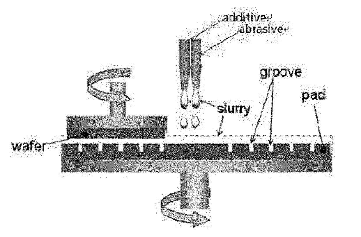
[0067]As an abrasive, colloidal silica was prepared, and an additive containing polyethylene glycol, a heterocyclic compound such as 5-methyl benzotriazole and an organic acid such as glutaric acid was mixed with deionized water as a solvent, whereby the abrasive and the additive were separately prepared to give a slurry composition for CMP suitable for polishing by adjusting the selectivity ratio of a silicon oxide film, a silicon nitride film and a polysilicon film through control of the amount of the additive via the additive line. The slurry composition for CMP thus obtained was added with a pH controller, namely KOH or HNO3, and thus the pH thereof was adjusted to 3.5. The amounts of the slurry components contained in the slurry composition for CMP are shown in Table 1 below.

examples 2 to 10

[0068]Slurry compositions for CMP were obtained in the same manner as in Example 1, with the exception that the kinds of additive and the amounts of abrasive, additive and solvent were changed. The amounts of the slurry components contained in the slurry compositions for CMP are shown in Table 1 below.

TABLE 1Additive (wt %)HeterocyclicColloidalOrganic acidcompoundsilicaPolyethylene(Glutaric(5-methyl(wt %)glycolacid)benzotriazole)pHEx. 120.50.0250.05 3.5Ex. 220.40.0250.0253.5Ex. 320.40.025—3.5Ex. 42 0.450.0250.0253.5Ex. 51.50.50.0250.05 3.5Ex. 620.20.025—3.5Ex. 72—0.025—3.5Ex. 82.50.80.025—3.5Ex. 93.01.00.50.0253.5Ex.103.51.41.00.0253.5

[0069]Evaluation of Polishing Rate Using CMP Slurry Composition

[0070]The polishing rates of a silicon oxide film, a silicon nitride film and a polysilicon film were evaluated using the CMP slurry compositions of Examples 1 to 10. Here, a CMP machine, made by CTS, was used.

[0071]The results of measurement of the polishing rates of a silicon oxide film, ...


PUM

PropertyMeasurementUnit
particle sizeaaaaaaaaaa
pHaaaaaaaaaa
particle sizeaaaaaaaaaa

Abstract

Provided are a slurry composition for CMP and a polishing method using the same, in which polishing can be performed by freely adjusting the selectivity ratio of a silicon oxide film, a silicon nitride and a polysilicon film through control of the amounts of additive and solvent, and thus the slurry composition can be efficiently applied to the process of manufacturing a semiconductor, requiring selective removal of a silicon nitride film and a polysilicon film relative to a silicon oxide film.

Description

TECHNICAL FIELD[0001]The present invention relates to a slurry composition for CMP and a polishing method using the same.BACKGROUND ART[0002]With an increase in the degree of integration of semiconductor devices, variation in the height of structures formed on a semiconductor wafer is increasing. In the case where such height variation is high, it is difficult to accurately print a mask pattern due to problems related to DOF (Depth Of Focus) in a subsequent lithography process.[0003]Thus, in order to flatten the surface of a wafer, chemical-mechanical polishing (hereinafter referred to as “CMP”), in which chemical removal processing and mechanical removal processing are combined into a single process, is widely utilized these days.[0004]Typically, a CMP process is performed in a manner in which a wafer surface having varying height is brought into close contact with a polishing pad, and a slurry, serving as a polishing liquid containing an abrasive and a chemical material, is then i...

Claims


Application Information

Patent Timeline
Patent Type & Authority Applications(United States)
IPC IPC(8): C09G1/02H01L21/306
CPCC09G1/02H01L21/30625H01L21/31053H01L21/3212C09K3/1463H01L21/304
Inventor LEE, SEUNG HUNLEE, SEUNG HYUNLEE, SU JINKIM, SEONG HWAN
Owner SKC CO LTD
Why Eureka
Try Eureka