
Higher containment vss with multi zone stripping

a technology of multi-zone stripping and containment, applied in the direction of separation process, dispersed particle separation, chemistry apparatus and processes, etc., can solve the problem of not only selectivity, but product composition between the two samples is enormous and very significant, and does not explain the high 15.6 wt, light cracking gas is being produced, etc., to achieve high degree of backmixing, low space velocity, and high residence time

Active Publication Date: 2018-07-26
MARATHON PETROLEUM
View PDF1 Cites 1 Cited by
  • Summary
  • Abstract
  • Description
  • Claims
  • Application Information

AI Technical Summary

Benefits of technology

The patent is about a new design for a high containment system that reduces the production of by-products in a petrochemical operation. The design changes include modifications to the stripper system to reduce the formation of coke and to control the space velocity and catalyst transport rates. These improvements can lead to higher yields of desired products and a reduction of harmful emissions. Additionally, the invention allows for the recovery and treatment of the stripper vent gas, which can be used to increase the efficiency of the system and produce higher yields of products. Overall, the patent describes a new and improved design for high containment systems that can enhance the production of desired products and reduce harmful emissions.

Problems solved by technology

Unlike the bulk of the contained riser products, the underflow and stripper material suffers additional catalytic cracking in a now less than desirable pseudo Dense Bed reactor configuration with a high degree of backmixing, low space velocity and high residence times. The change in not only selectivity, but product composition between the two samples is enormous and very significant.
However, all this undesirable secondary catalytic cracking of the riser products does not explain the high 15.6 Wt% dry gas production.
Secondly, we can now determine the light cracked gas that's being produced in these secondary pseudo Dense Bed reactors and strippers.
Yet none of the previous, cold flow modeling work associated with FCC strippers appear to have taken into account the magnitude of this inert, extremely low molecular weight, material that's being continuously produced from the catalyst's surface.
A dense fluidized bed has many unique and beneficial characteristics; but the high degree of axial solids mixing along with low contacting efficiency between the bubbling gas phase and the solid emulsion phase, can be quite detrimental.
This axial turnover rate, or backmixing in a vigorously bubbling and flowing bed, can become extremely high and very detrimental to high containment of the reactor products and efficient counter current “plug flow” stripping.
Since ε=U / (U+UB−UL), the void fraction ε will approach 1.0 when the velocity of the emulsion phase approaches the bubble rise velocity, and this can lead to flow instability in lower strippers and standpipes.
At superficial gas velocities much greater than 1 ft / sec, the bubble rise velocity can become limiting.
As predicted, flow instability occurred along with reduced stripping efficiencies above certain catalyst fluxes.
However, none of these studies appear to have considered the significant impact of the secondary “cracked gas” reactions, “J” values and the beds freeboard activity would have on riser product underflows and stripping efficiency.

Method used


Image

  • Higher containment vss with multi zone stripping
  • Higher containment vss with multi zone stripping
  • Higher containment vss with multi zone stripping

Examples


Embodiment Construction

)

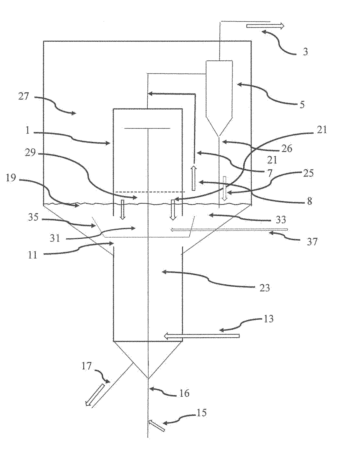
[0059]FIG. 1 is a schematic representation of a typical high containment VSS and reactor stripper configuration. Feed injection nozzles 15 inject feed into a flowing stream of catalyst. The resulting suspension reacts rapidly and flows through a plug flow riser reactor 16 into the VSS separation chamber 1 where most of the catalyst is separated. The catalyst then flows down into the stripper section 23 along with some hydrocarbon underflow 21 that is still contained within the catalyst voids. The majority of the hydrocarbon vapor products and any entrained catalyst then pass through several single stage cyclones 5 housed within the reactor vessel 27 for final catalyst separation prior to entering the combined vapor product line 3. This entrained catalyst then flows from the cyclones through diplegs 26 into the catalyst bed 19 located in the outer annulus section of the reactor vessel 27. The vapor flow 8 in the reactor vessel 27 contains some but not all of the entrained hydrocarbo...


PUM

PropertyMeasurementUnit
superficial gas velocityaaaaaaaaaa
octane numberaaaaaaaaaa
resonance time distributionaaaaaaaaaa

Abstract

This patent application discloses engineering design modifications to the VSS exit, stripper entrance and the primary cyclone diplegs that can significantly reduce the underflow of reactor riser products into the stripper and reactor vessel and thereby produce higher desired product selectivities, improved stripping efficiency and a stripper vent gas, that continuously flows through the reactor vessel, with a low coke forming potential due to its low concentration of ethylene and higher molecular weight material, that could, if desired, be recovered separately from the primary riser products.

Description

CROSS REFERENCE TO RELATED APPLICATION[0001]The present patent application is based upon and claims the benefit of provisional patent application No. 62 / 345,712, filed on Jun. 3, 2016.FIELD OF THE INVENTION[0002]The present invention discloses engineering design modifications to the vortex separation system (VSS) exit, stripper entrance and the primary cyclone diplegs that can significantly reduce the underflow of reactor riser products into the stripper and reactor vessel and thereby produce higher desired product selectivities, improved stripping efficiency and a stripper vent gas, that continuously flows through the reactor vessel, with a low coke forming potential due to its low concentration of ethylene and higher molecular weight material, that could, if desired, be recovered separately from the primary riser products.BACKGROUND OF THE INVENTION[0003]Over the years, the FCC reactor section has been developed from Bed and Riser Systems to various current High Containment Config...

Claims


Application Information

Patent Timeline
Patent Type & Authority Applications(United States)
IPC IPC(8): C10G11/05B01D45/16C10B3/00C10G11/18
CPCC10G11/05C10G11/18C10B3/00B01D45/16B01J8/1872
Inventor LOMAS, DAVID
Owner MARATHON PETROLEUM
Learn More