
Focus ring and method for producing focus ring

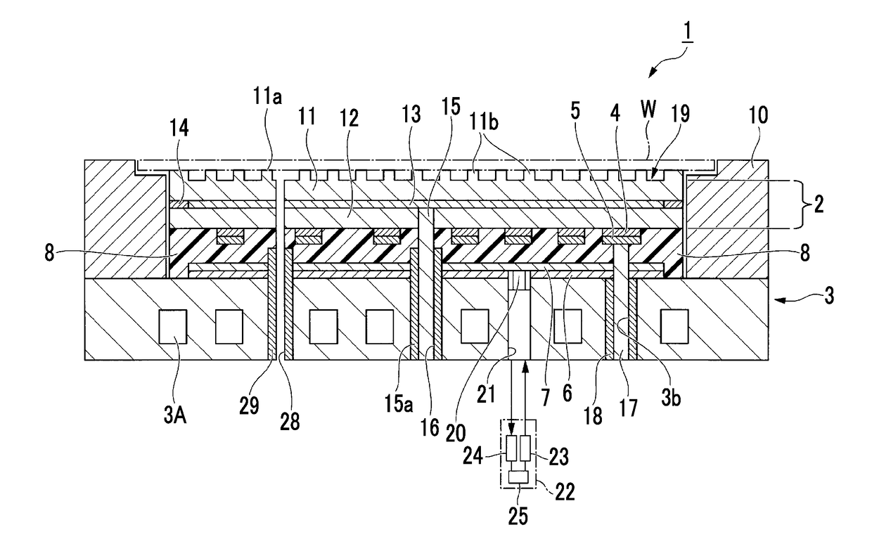
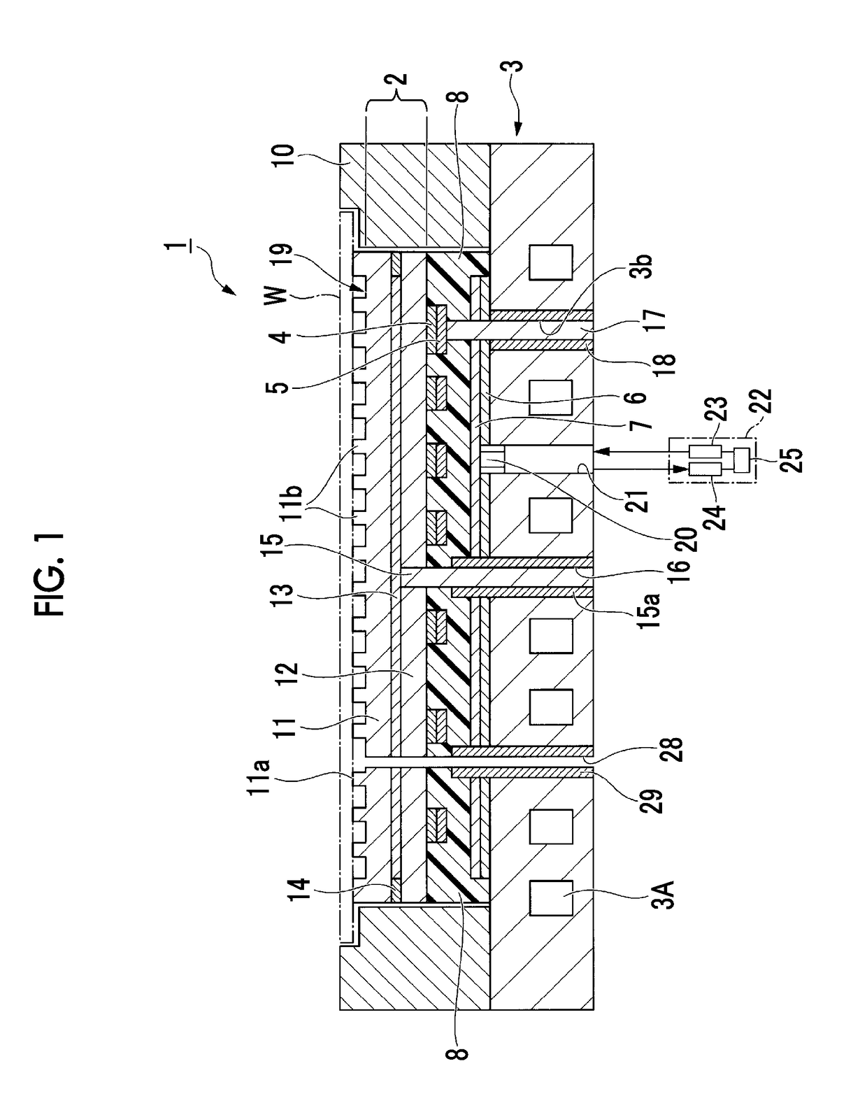
a focus ring and focus ring technology, applied in the direction of carbon-silicon compound conductors, electric discharge tubes, electrical equipment, etc., can solve the problems of unstable treatment conditions of plasma steps and temperature changes of focus rings, and achieve favorable plasma resistance, easy production, and favorable plasma resistance

Active Publication Date: 2018-07-19
SUMITOMO OSAKA CEMENT CO LTD
View PDF0 Cites 12 Cited by
  • Summary
  • Abstract
  • Description
  • Claims
  • Application Information

AI Technical Summary

Benefits of technology

The present invention is about a focus ring that is resistant to plasma, which can damage the ring during certain processes. The invention also provides a method to easily produce these resistant focus rings.

Problems solved by technology

Furthermore, there has been a problem in that, due to changes in the shapes of focus rings caused by heat and consumption, changes in the thermal conductivities of focus rings and focus ring-loading surfaces cause temperature changes of focus rings, and the treatment conditions of plasma steps become unstable.

Method used


Image

  • Focus ring and method for producing focus ring
  • Focus ring and method for producing focus ring

Examples


example 1

[0124]α-SiC powder having an average particle diameter of 0.8 μm and β-SiC powder having an average particle diameter of 0.05 μm (thermal plasma CVD powder) were preliminarily mixed together in an α-SiC powder to β-SiC powder mass ratio of 10:1 and were then dispersed in water, thereby producing a dispersion liquid.

[0125]Next, the obtained dispersion liquid was crushed and mixed using a two-stream particle collision-type crushing and mixing apparatus, and was then granulated and dried by means of spray drying, thereby obtaining mixed powder of the α-SiC powder and the β-SiC powder.

[0126]Next, the obtained mixed powder was molded and was sintered under conditions of a temperature of 2,400° C. and a pressure of 40 MPa in an argon atmosphere for four hours, thereby obtaining a sintered body having φ370 mm. Meanwhile, the temperature-rise rate from 1,400° C. to 2,000° C. during the sintering was set to 15° C. / minute.

[0127]The outer circumference and both surfaces of the obtained sintere...

example 2

[0134]A sintered body of Example 2 was obtained in the same manner as in Example 1 except for the fact that the mixing ratio of the α-SiC powder to the β-SiC powder was set to 10:3 (the α-SiC powder:the β-SiC powder) in terms of the mass ratio.

[0135]The obtained sintered body was measured on the basis of Example 1. The test results are shown in Table 1.

example 3

[0136]A sintered body of Example 3 was obtained in the same manner as in Example 1 except for the fact that the β-SiC powder was not used and only the α-SiC powder was used.

[0137]The obtained sintered body was measured on the basis of Example 1. The test results are shown in Table 1.


PUM

PropertyMeasurementUnit
volume-average crystallite diameteraaaaaaaaaa
particle diameteraaaaaaaaaa

Abstract

The present invention provides a focus ring having favorable plasma resistance. In addition, the present invention provides a method for producing a focus ring which enables the easy production of focus rings having favorable plasma resistance. The focus ring of the present invention is a focus ring made of a sintered body of silicon carbide, in which the sintered body includes a plurality of first crystal grains having an α-SiC-type crystal structure and a plurality of second crystal grains having a β-SiC-type crystal structure, a content of the first crystal grains is 70% by volume or more of a total of the first crystal grains and the second crystal grains, and a volume-average crystallite diameter of the first crystal grains is 10 μm or less.

Description

TECHNICAL FIELD[0001]The present invention relates to a focus ring and a method for producing a focus ring.BACKGROUND ART[0002]Recently, in semiconductor production apparatuses in which plasma steps are carried out, electrostatic chuck devices capable of easily mounting and fixing wafers on and to a sample platform and capable of maintaining the wafers at desired temperatures have been used. These electrostatic chuck devices include, in the upper portion, a ring member which surrounds a wafer-loading surface and is disposed at an outer circumferential edge portion of a wafer adsorption portion (focus ring).[0003]In a state in which a wafer is placed in an electrostatic chuck device, the focus ring is disposed so as to surround the outer circumference of the wafer in a plan view. Therefore, when a forming material of the focus ring is selected, in the circumferential edge portion of the wafer, it is possible to form an electrical environment for plasma which is substantially the same...

Claims


Application Information

Patent Timeline
Patent Type & Authority Applications(United States)
IPC IPC(8): C04B35/565C04B35/645H01L21/683
CPCC04B35/565C04B35/645H01L21/6833C04B2235/383C04B2235/3834C04B2235/5436C04B2235/5445C04B2235/6562C04B2235/786H01J37/32642C04B35/5755C04B2235/5454C04B2235/5472C04B2235/72C04B2235/94H01B1/04H01L21/3065
Inventor NAGATOMO, HIROAKI
Owner SUMITOMO OSAKA CEMENT CO LTD
Learn More