Machine learning based model localization system

Active Publication Date: 2018-07-05
MANOR FINANCIAL INC
View PDF9 Cites 43 Cited by
  • Summary
  • Abstract
  • Description
  • Claims
  • Application Information

AI Technical Summary

Benefits of technology

The patent describes a system that can accurately match depth and scale of virtual objects in a real-scenes using machine learning algorithms. This allows for seamless placement of virtual objects in the scene and provides information about their orientation and location relative to the viewer. The system uses a depth map of the scene and object recognition algorithms to identify specific objects and their context in the scene, such as room boundaries and floor planes. This information helps in understanding the scene better and improves the accuracy of augmented reality systems. Compared to existing methods, this approach is faster, more accurate and cost-effective.

Problems solved by technology

However, physical markers must be printed, which is cumbersome.
Additionally, for static images, markers must be placed in a scene prior to capturing an image and the marker position & orientation cannot be altered after image capture.
3D sensors have proven costly, bulky, and complex.
Such software has proven computationally expensive.
However, the disclosed system, typical of all stereoscopic imaging systems, requires complex optics and the computationally intensive transmission and correlation of a stereoscopic image pair.
The method is reliant on a stereo-image pair and thus cannot be used to derive a pose estimate from a 2D image.
While this class of device inherently provides a direct and sometimes accurate imaging device pose estimates, the hardware is generally expensive, bulky, and power intensive, and therefore are not practical for mobile device applications.
Users typically capture static images and dynamic video without the intent of using this data for AR applications, and as a result there are numerous image and video files available that lack the requisite 3D scene metadata needed for realistic dynamic overlay of AR content integration into the image.
Thus, reliance on 3D imaging device-based pose estimates (i.e. sensors that encode pose measurement data into the image file) also precludes the derivation of pose estimates from images captured on standard 2D camera systems.
However, most mobile devices use monocular cameras, and thus the vast majority of image content captured by users is limited to 2D.
However, this method requires complex computer vision software operating on multiple 2D images, generally taken from a video stream or requiring the user to capture a sequence of individual static images from sufficiently different perspectives while ensuring the scene content remains largely static.
Thus, the method is computationally expensive, sometimes labor intensive, and the generation of a 3D map or derivation of the camera pose estimate from a single image is not achievable using such methods.

Method used


Image

  • Machine learning based model localization system
  • Machine learning based model localization system
  • Machine learning based model localization system

Examples


Embodiment Construction

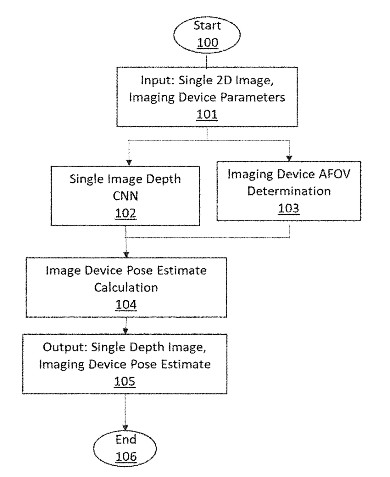
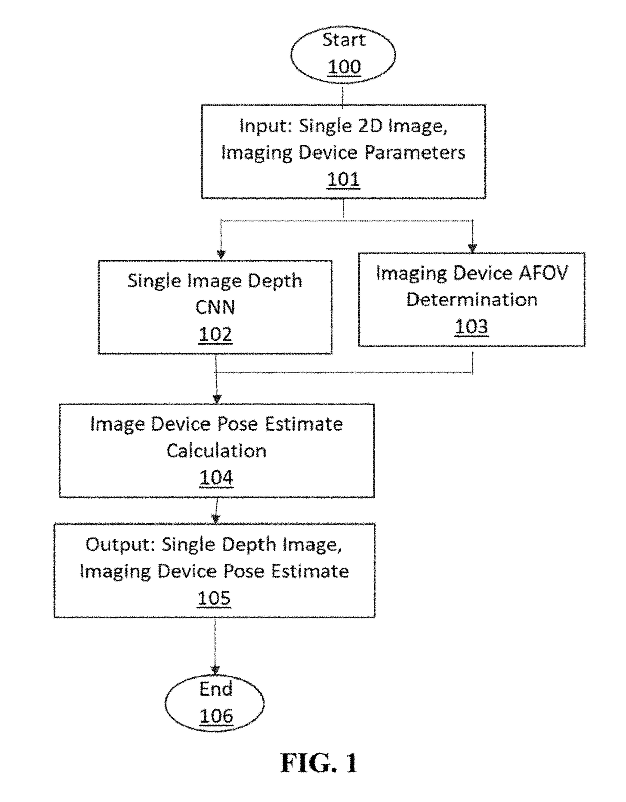
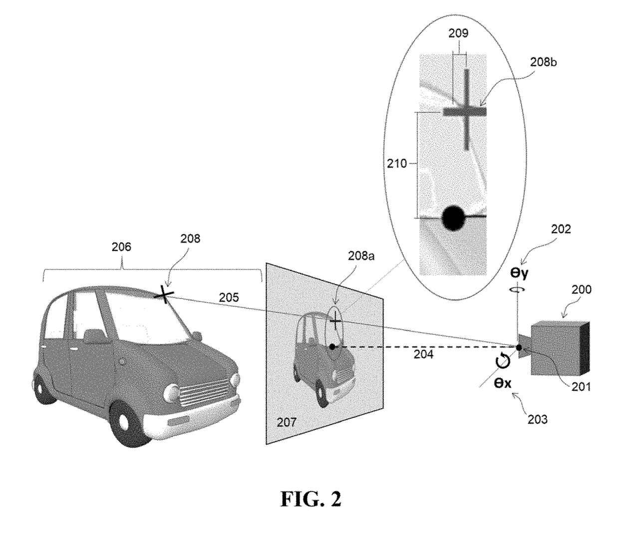
[0028]A method and exemplary implementation system for generating an accurate 3D pose estimate of a source image sensor relative to 3D objects in an observed scene, based on a 2D source image input, is described. Referring to the figures, like numerals indicate like or corresponding parts throughout several views. Many specific details are set forth in order to provide a thorough understanding of the embodiments described herein, but it is understood by those of ordinary skill in the art that the embodiments described herein may be practiced without these specific details. Further, in other instances, well-known optional features (i.e. methods, procedures and components) have not been described in detail so as not to obscure the embodiments described herein, but it is understood by those of ordinary skill in the art that such optional features may be practiced in conjunction with the disclosed invention. The description is not to be considered as limiting the scope of the embodiment...


PUM


Abstract

A method for deriving an image sensor's 3D pose estimate from a 2D scene image input includes at least one Machine Learning algorithm trained a priori to generate a 3D depth map estimate from the 2D image input, which is used in conjunction with physical attributes of the source imaging device to make an accurate estimate of the imaging device 3D location and orientation relative to the 3D content of the imaged scene. The system may optionally employ additional Machine Learning algorithms to recognize objects within the scene to further infer contextual information about the scene, such as the image sensor pose estimate relative to the floor plane or the gravity vector. The resultant refined imaging device localization data can be applied to static (picture) or dynamic (video), 2D or 3D images, and is useful in many applications, most specifically for the purposes of improving the realism and accuracy of primarily static, but also dynamic Augmented Reality (AR) applications.

Description

CROSS REFERENCE TO RELATED APPLICATIONS[0001]This application claims priority from U.S. Provisional Application No. 62 / 508,446 filed May 19, 2017, entitled “ARTIFICIAL NEURAL NETWORK BASED MODELING & LOCALIZATION SYSTEM.” The content of the aforementioned application is hereby expressly incorporated by reference into the present application in its entirety.FIELD OF THE INVENTION[0002]The invention relates generally to a method for localizing and globally orienting an imaging device (e.g. a camera) in an observed environment based on analysis conducted by a trainable automated system on at least one 2-Dimensional image of a scene within the subject environment.BACKGROUND OF THE INVENTION[0003]Augmented Reality (AR) is a mode of Human Computer Interaction in which virtual content is overlaid onto a user's visual perception of their local environment such that the virtual content appears to be physically present in a given scene. The overlay may occur on static images in an offline mod...

Claims


Application Information

Patent Timeline
IPC IPC(8): G06T7/70G06N3/08G06N3/04G06T7/536
CPCG06T7/70G06N3/08G06N3/04G06T7/536G06T2207/30244G06T2207/20081G06T2207/20084G06T7/77G06T7/50
Inventor CLARK, TAYLORKEMENDO, ANDREWSHANKS, MARK
Owner MANOR FINANCIAL INC
Why Eureka
Try Eureka