
Passively q-switched fiber laser system and method for fabricating a saturable absorber of the system

a fiber laser and q-switched technology, applied in the direction of laser details, active medium shape and construction, electrical equipment, etc., can solve the problems of large and complex fiber pigtail acousto-optic or electric optic devices, large operating wavelength ranges, and high cost and complexity of systems, so as to increase the maximum output power and pulse energy of pulsed laser beams

Active Publication Date: 2018-05-03
NAT TAIPEI UNIV OF TECH
View PDF0 Cites 7 Cited by
  • Summary
  • Abstract
  • Description
  • Claims
  • Application Information

AI Technical Summary

Benefits of technology

The patent is about a fiber laser system that uses a special material called a saturable absorber to increase the power and energy of laser pulses. The system is designed to have a wide range of operation wavelengths, and the saturable absorber can be easily fabricated using a simple method. This allows the laser system to have multiple operation bands and enhance its performance. Additionally, the novel saturable absorber has low saturable absorption intensity, making it cost-effective and suitable for use with different doped ions or emission wavelength regions.

Problems solved by technology

In actively Q-switched fiber laser systems, extensive and complex fiber pigtailed acousto-optic or electric optic devices are generally required.
In such fiber laser systems, the use of high voltages and radio-frequency trigger sources makes these systems expensive and complex.
Although SESAMs have been widely used and commercialized, their operation wavelength ranges are relatively small, they are expensive and they has a complicated processing.
Although CNTs have a low saturation energy and a fast recovery, their absorbable bandwidths are relatively narrow and they are easy to be damaged.

Method used


Image

  • Passively q-switched fiber laser system and method for fabricating a saturable absorber of the system
  • Passively q-switched fiber laser system and method for fabricating a saturable absorber of the system
  • Passively q-switched fiber laser system and method for fabricating a saturable absorber of the system

Examples


first embodiment

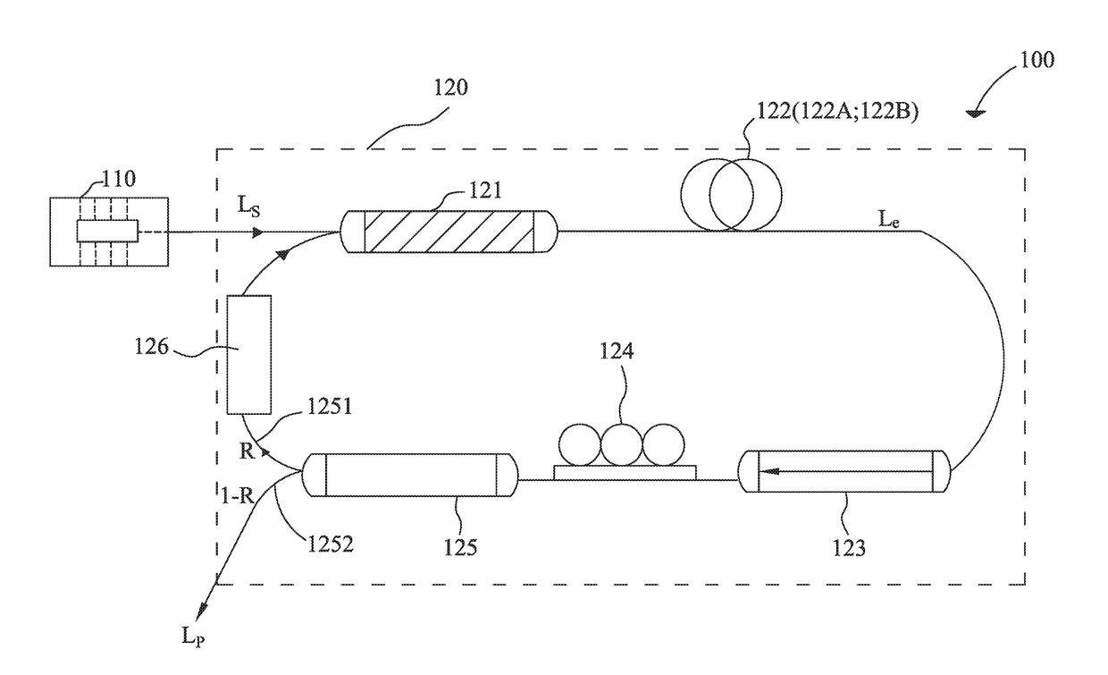
[0032]FIG. 1 is a schematic view of the passively Q-switched fiber laser system according to the first embodiment of the present invention. The passively Q-switched fiber laser system 100 comprises a pump source 110 and a ring cavity 120. The pump source 110 is directly connected to the ring cavity 120. In the first embodiment, the pump source 110 is a semiconductor laser with 155 mW power and can generate a continual laser beam with a wavelength of 976 nm, the continual laser beam is called pump beam LS as below and serves as an incident beam of the ring cavity 120. The ring cavity 120 comprises a wavelength division multiplexer 121, a gain fiber 122, an optical isolator 123, a polarization controller 124, a directional coupler 125 and a saturable absorber 126 connected in order, wherein the saturable absorber 126 is connected between the directional coupler 125 and the wavelength division multiplexer 121 to form a ring structure. The ring cavity 120 has a total length of 10 meters...

second embodiment

The Second Embodiment

[0044]As shown by the absorption spectrum of the PbS QD polymer composite film 126a in FIG. 3, it can be seen that there is also a strong absorption at the wavelength of 1064 nm, and the pulsed laser beam with the wavelength of 1064 nm is widely applied in biomedical and cosmetics fields, so the passively Q-switched fiber laser system 100 employs the PbS quantum-dot polymer composite film 126a as its saturable absorber 126. Different from the first embodiment, in the second embodiment, the erbium-doped fiber 122A is changed to ytterbium-doped fiber 122B with the same length of 2 meters, and in this two embodiments, only the gain fiber is different, other elements and configurations are the same. In the second embodiment, the ytterbium ion (Yb3+) in the ytterbium-doped fiber 122B is stimulated by the pump beam LS with a wavelength of 976 nm to release a stimulated laser beam Le with a wavelength of 1.064 μm. And, the pulsed laser beam LP is produced by passively ...

third embodiment

The Third Embodiment

[0046]Different from the second embodiment, in the third embodiment, the ytterbium-doped fiber 122B is changed to ytterbium-doped fiber 122B with the same length of 50 cm, and the passively Q-switched fiber laser system 100 is optimized by equipping with the directional coupler with different reflectivity R, wherein other elements and configurations are all the same as the second embodiment. The ytterbium-doped fiber 122B with a length of 50 cm may completely absorb the pump beam without existing the problem of self-absorption.

[0047]When the reflectivity R is 50%, increasing the pump power from 109 mW to 156 mW, the repetition frequency of the passively Q-switched fiber laser system 100 increases from 14.43 kHz to 31.57 kHz, and the pulse bandwidth decreases from 8.44 μs to 2.53 μm. When the pump power is 156 mW, the average output power of the ytterbium-doped fiber reaches 12.34 mW, and the slop efficiency is 21.63%. When the pump power is 153 mW, the peak power...


PUM

PropertyMeasurementUnit
wavelengthaaaaaaaaaa
wavelength rangeaaaaaaaaaa

Abstract

A passively Q-switched fiber laser system comprises a pump source and an ring cavity connected with each other. The ring cavity comprises a gain fiber, a directional coupler and a saturable absorber connected in order. The saturable absorber is a quantum-dot polymer composite film, which is fabricated by a simple method comprising steps of: mixing a quantum dot material of lead sulfide (PbS) with a colloidal polymer to form a mixture; and drying the mixture at two different temperatures in two stages respectively. The saturable absorber of the present invention has lower saturating intensity and a plurality of absorption bands comprising 1000 nm to 1100 nm and 1500 nm to 1600 nm. The maximum output power and the maximum pulse energy of the passively Q-switched fiber laser system can be superior to those laser systems using the quantum-dot (QD) polymer composite film as saturable absorber.

Description

STATEMENT REGARDING PRIOR DISCLOSURES BY THE INVENTOR OR A JOINT INVENTOR[0001]The following disclosure(s) are submitted under 35 U.S.C. § 102(b)(1)(A):DISCLOSURE(S)[0002](1) Yin-Wen Lee, Chien-Ming Chen, Chia-Wei Huang, Shih-Ken Chen, and Jhang-Rong Jiang, “Passively Q-switched Er3+-doped fiber lasers using colloidal PbS quantum dot saturable absorber,” OPTICS EXPRESS Vol. 24, No. 10, 10675-10681 (2016).BACKGROUND OF THE INVENTION(1) Field of the Invention[0003]The present invention relates to a fiber laser system and a method for fabricating an operating element of the fiber laser system, in particular, to a passively Q-switched fiber laser system applying a novel saturable absorber as the operating element, and a method for fabricating the novel saturable absorber.(2) Description of the Prior Art[0004]Fiber laser has brought about many breakthroughs and progresses into the field of laser application, has replaced gas laser and traditional solid laser gradually and has become a te...

Claims


Application Information

Patent Timeline
Patent Type & Authority Applications(United States)
IPC IPC(8): H01S3/11H01S3/067H01S3/10
CPCH01S3/1115H01S3/10061H01S3/06791H01S3/06712H01S3/10046H01S3/113H01S3/1608
Inventor CHEN, CHIEN-MINGLEE, YIN-WENHUANG, CHIA-WEICHEN, SHIH-KENJIANG, JHANG-RONG
Owner NAT TAIPEI UNIV OF TECH
Learn More