
Dielectric resonator antenna and method of making the same

a resonator antenna and dielectric technology, applied in the direction of antennas, antenna earthings, electrical devices, etc., can solve the problems of limited bandwidth, limited efficiency, limited gain,

Active Publication Date: 2018-04-26
ROGERS CORP
View PDF0 Cites 32 Cited by
  • Summary
  • Abstract
  • Description
  • Claims
  • Application Information

AI Technical Summary

Benefits of technology

This patent describes a type of antenna that uses layers of dielectric material to produce a main electromagnetic field component in response to an electrical signal. The antenna has a signal feed that is electromagnetically coupled to the layers of dielectric materials. One of the layers has a non-gaseous dielectric material with a smaller dielectric constant than the non-gaseous dielectric material in the main body of the antenna. The non-gaseous dielectric material has a smaller cross-sectional height and width, resulting in a more compact antenna design. The patent also describes a DRA array with multiple antennas spaced apart from each other. The technical effects of the patent focus on the design and structure of the antenna, which can make it more efficient and compact while still producing a strong signal.

Problems solved by technology

Existing resonators and arrays employ patch antennas, and while such antennas may be suitable for their intended purpose, they also have drawbacks, such as limited bandwidth, limited efficiency, and therefore limited gain.
Techniques that have been employed to improve the bandwidth for particular applications have typically led to expensive and complicated multilayer and multi-patch designs, and it remains challenging to achieve desired bandwidths for such particular applications, which may, but not necessarily, include bandwidths greater than 25%.
Furthermore, multilayer designs add to unit cell intrinsic losses, and therefore reduce the antenna gain.
Additionally, patch and multi-patch antenna arrays employing a complicated combination of metal and dielectric substrates make them difficult to produce using newer manufacturing techniques available today, such as three-dimensional (3D) printing (also known as additive manufacturing).

Method used


Image

  • Dielectric resonator antenna and method of making the same
  • Dielectric resonator antenna and method of making the same
  • Dielectric resonator antenna and method of making the same

Examples


Embodiment Construction

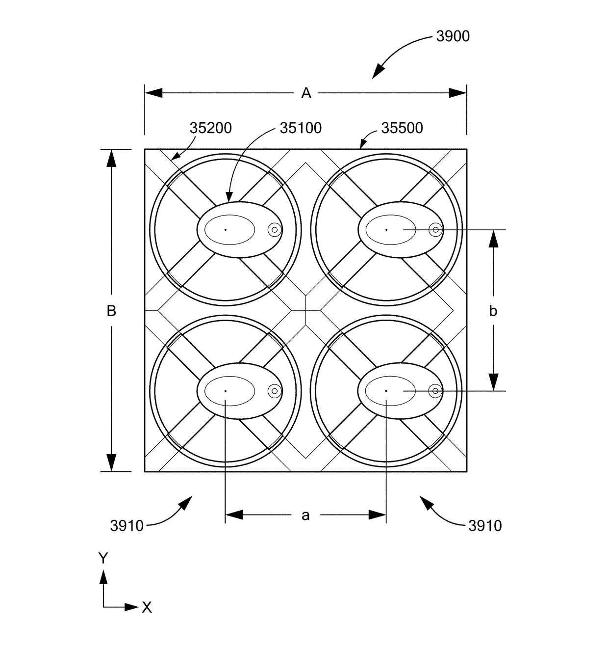
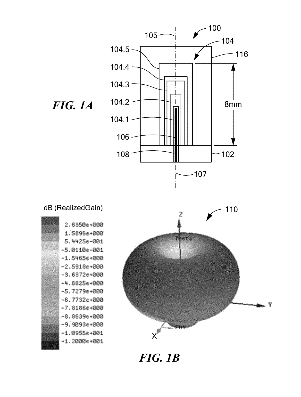
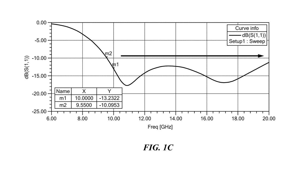
[0082]Embodiments disclosed herein include different arrangements useful for building broadband dielectric resonator antenna (DRA) arrays, where the different arrangements employ a common structure of dielectric layers having different thicknesses, different dielectric constants, or both different thicknesses and different dielectric constants. The particular shape of a multilayer DRA depends on the chosen dielectric constants for each layer. Each multilayer shell may be cylindrical, ellipsoid, ovaloid, dome-shaped or hemispherical, for example, or may be any other shape suitable for a purpose disclosed herein. Broad bandwidths (greater than 50% for example) can be achieved by changing the dielectric constants over the different layered shells, from a first relative minimum at the core, to a relative maximum between the core and the outer layer, back to a second relative minimum at the outer layer. A balanced gain can be achieved by employing a shifted shell configuration, or by emp...


PUM


Abstract

A dielectric resonator antenna (DRA) includes a plurality of volumes of dielectric materials having N volumes, N being an integer equal to or greater than 3, disposed to form successive and sequential layered volumes V(i), i being an integer from 1 to N, and a signal feed disposed to produce a main E-field component having a defined direction, Ē, in the DRA. The N volumes include a non-gaseous dielectric material, and have an inner region with a dielectric constant that is less than the dielectric constant of the non-gaseous dielectric material. The inner region has a cross sectional overall height Hr, and a cross sectional overall width Wr in a direction parallel to Ē, and the volume of non-gaseous dielectric material has a cross sectional overall height Hv, and a cross sectional overall width Wv in a direction parallel to Ē, wherein Hr is greater than Wr / 2.

Description

CROSS REFERENCE TO RELATED APPLICATIONS[0001]This application is a continuation-in-part of U.S. application Ser. No. 15 / 334,669, filed Oct. 26, 2016, which claims the benefit of priority of: U.S. Provisional Application Ser. No. 62 / 247,459, filed Oct. 28, 2015; U.S. Provisional Application Ser. No. 62 / 258,029, filed Nov. 20, 2015; and, U.S. Provisional Application Ser. No. 62 / 362,210, filed Jul. 14, 2016, all of which are incorporated herein by reference in their entireties.BACKGROUND OF THE INVENTION[0002]The present disclosure relates generally to a dielectric resonator antenna (DRA), particularly to a multiple layer DRA, and more particularly to a broadband multiple layer DRA for microwave and millimeter wave applications.[0003]Existing resonators and arrays employ patch antennas, and while such antennas may be suitable for their intended purpose, they also have drawbacks, such as limited bandwidth, limited efficiency, and therefore limited gain. Techniques that have been employe...

Claims


Application Information

Patent Timeline
Patent Type & Authority Applications(United States)
IPC IPC(8): H01Q9/04H01Q1/48H01Q15/14H01Q21/06
CPCH01Q9/0485H01Q1/48H01Q15/14H01Q21/061H01Q19/10
Inventor PANCE, KRISTISPRENTALL, KARL E.WILLIAMS, SHAWN P.DAIGLE, ROBERT C.O'CONNOR, STEPHENTARASCHI, GIANNI
Owner ROGERS CORP
Learn More