
Catalyst preparation unit for use in processing of heavy hydrocarbons

Active Publication Date: 2018-03-29
PC CUPS LTD
View PDF3 Cites 2 Cited by
  • Summary
  • Abstract
  • Description
  • Claims
  • Application Information

AI Technical Summary

Benefits of technology

The patent describes a system for mixing and conveying catalyst reactants and hydrocarbons. The system includes a mill to reduce the size of the reactants and a high shear mixer to further reduce the particle size. This technology allows for more efficient and effective mixing of the reactants, resulting in improved performance of the catalyst.

Problems solved by technology

While effective in many applications, supported catalysts are at a disadvantage when used with feedstocks that inevitably produce solid deposits within the porous network of the catalyst support.
In such cases a progressive loss of catalyst performance due to pore plugging occurs, making larger quantities of catalysts required for a given process to maintain efficient reactions.
In reactions where unsupported catalysts are soluble in the reaction media, difficulties in recovery of the catalysts from the product stream increase reaction or production costs because the catalysts must be replaced.
There may also be a requirement for the reactants to be subjected to costly separation processes.
Frequently, unsupported metal based catalysts with equivalent particle sizes or diameters to supported catalysts offer lower surface area of catalytic active phases.
However, the risk of contact between fluids from in situ combustion and synthesis gas or hydrogen at a high temperature is an important challenge for the control of that process.
The abovementioned investigations did not provide solutions to major challenges of a real-world upgrading process.
This last challenge involves the maintenance of an economic process while reducing coke formation that at the same time is the cause and consequence of catalyst deactivation.
As such, one of the existing main challenges is the rapid deactivation or poisoning of the catalyst due to the large amount of contaminants such as: asphaltenes, sulfur and metals (Galarraga, C. E. and P. Pereira-Almao, Hydrocracking of Athabasca bitumen using submicronic multimetallic catalysts at near in-reservoir conditions.
Another challenge involves the transport of heat to the reservoir in a conventional (non-electrical) and continuous manner, without incurring large costs of energy transfer and while ensuring production with a stable increase in quality and crude oil.
At the same time, this process produces olefins in significant amounts when insufficient levels of hydrogen are present.
Most notably, the surfactant that could be used in the preparation of the ultra-dispersed catalysts does not decompose entirely under the tested conditions, and that it had a tendency to form emulsions within a packed bed (previously saturated with water), precipitating some particles causing blocking of the packing, especially at its entrance.
As a result, a number of problems must be addressed to take full advantage of the technology.
One such problem is a requirement for a catalyst preparation unit with sufficient flexibility to produce hydrocarbon processing catalysts efficiently and at relatively low cost.

Method used


Image

  • Catalyst preparation unit for use in processing of heavy hydrocarbons
  • Catalyst preparation unit for use in processing of heavy hydrocarbons
  • Catalyst preparation unit for use in processing of heavy hydrocarbons

Examples


embodiment 1

paration Unit for Preparation of Tri-Metallic Catalyst

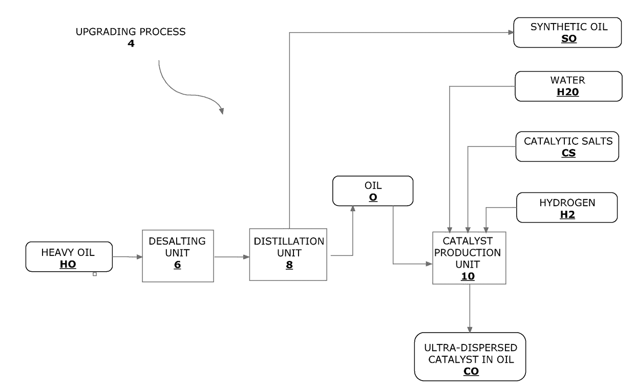
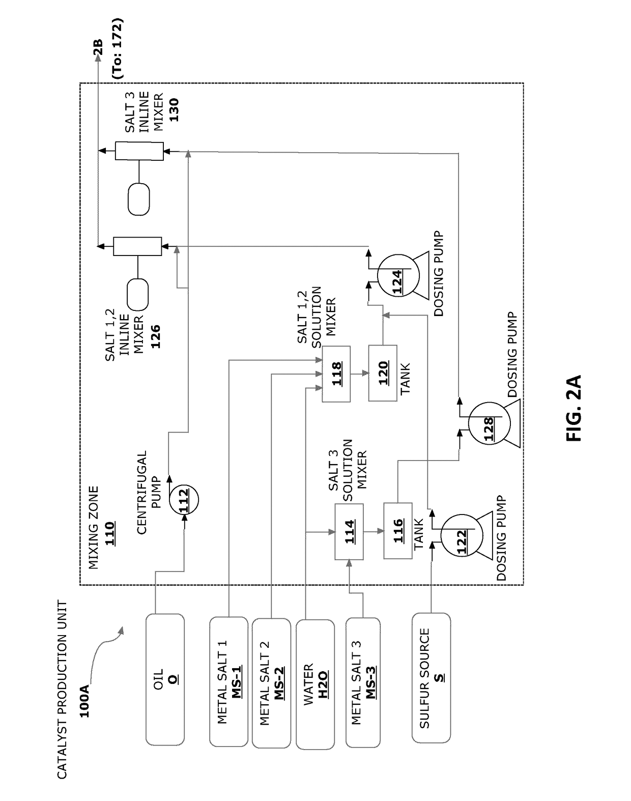
[0075]According to one embodiment of the present invention, a catalyst preparation unit is provided which is designed to prepare ultra-dispersed catalyst in oil according to a process designated herein as “preparation of tri-metallic catalyst.” This embodiment of the catalyst preparation unit is shown in two parts (100A and 100B) in FIGS. 2A and 2B, respectively. One particular example of a process for production of a trimetallic catalyst is the production of Ni—W(S)MoO3 catalyst which is described in Example 4 of U.S. Pat. No. 7,897,537 which is incorporated herein by reference in entirety. The present embodiment is an appropriate platform for producing this and other similar metal-based hydrocarbon processing catalysts.

[0076]Turning now to FIG. 2A, which shows part 100A of the catalyst preparation unit, it is seen that material inputs into this part 100A of the catalyst preparation unit include an oil O (which may be a heavy oi...

embodiment 2

paration Unit for a Salt Composite Feed Process

[0084]According to another embodiment of the present invention, a catalyst preparation unit is provided which is designed to prepare ultra-dispersed catalyst in oil according to a process designated herein as “salt composite feed.” In a manner similar to FIGS. 2A and 2B, the present embodiment of the catalyst preparation unit is shown in two parts (200A and 200B) in FIGS. 3A and 3B, respectively.

[0085]Turning now to FIG. 3A, there is shown a mixing zone 210 in part 200A of the catalyst preparation unit. It is seen that material inputs include an oil O (which may be a heavy oil fraction or vacuum distillation residue or similar sample), and a mixture of three different metal salts, each in solid form and one or more compounds providing a reactant source of sulfur. This mixture is referred to as a “metal salt composite” MS-C.

[0086]The metal salt composite MS-C is conveyed to a mill 234 whose function is to grind the solids to reduce parti...

embodiment 3

paration Unit for a Mono-Metallic Catalyst Preparation Process

[0091]According to another embodiment of the present invention, a catalyst preparation unit is provided which is designed to prepare ultra-dispersed catalyst in oil according to a process designated herein as “mono-metallic catalyst preparation.” In a manner similar to FIGS. 2A and 2B as well as FIGS. 3A and 3B, the present embodiment of the catalyst preparation unit is shown in three parts (300A and 300B and 300C) in FIGS. 4A, 4B and 4C, respectively. This embodiment provides a mixture of three different mono-metallic catalyst compounds by separate reactions of three different metal salt compounds with a sulfur source compound. However, the skilled person will recognize that alternative embodiments are possible wherein only one, only two or more than three metal salts are used to generate distinct mono-metallic catalyst compounds. Therefore, alternative embodiments are contemplated wherein fewer or more catalyst reactant...


PUM

PropertyMeasurementUnit
Angleaaaaaaaaaa
Angleaaaaaaaaaa
Angleaaaaaaaaaa

Abstract

A catalyst preparation unit for producing an activated hydrocarbon-catalyst mixture. The catalyst preparation unit includes one or more catalyst reactant input conduits; a hydrocarbon input conduit; a water input conduit; one or more catalyst reactant mixing and conveyance systems for receiving and mixing catalyst reactants from the catalyst component input conduits and water provided by the water input conduit to provide one or more catalyst reactant solutions; one or more hydrocarbon mixing and conveyance systems for receiving and mixing the catalyst reactant solutions and hydrocarbons provided by the hydrocarbon input conduit to produce a hydrocarbon-catalyst reactant mixture; at least one reactor located downstream of the mixers, for receiving and activating the hydrocarbon-catalyst reactant mixture, thereby producing the activated hydrocarbon catalyst mixture; a gas / liquid separator located downstream of the reactor, for removing vapors and gas from the activated hydrocarbon-catalyst mixture; and an output conduit for transporting the activated hydrocarbon-catalyst mixture away from the catalyst preparation unit.

Description

FIELD OF THE INVENTION[0001]The invention relates to the field of processing of hydrocarbons and provides a catalyst preparation unit for producing a mixture of activated catalyst for this purpose.BACKGROUND OF THE INVENTION[0002]The use of catalysts in the processing of hydrocarbons is well known. Catalysts enable hydrocarbon processing reactions, such as hydro-treating, hydrocracking, steam cracking or upgrading reactions, to proceed more efficiently under various reaction conditions with the result that the overall efficiency and economics of a process are enhanced. Different catalysts are more effective in certain reactions than others and, as a result, significant research is conducted into the design of catalysts in order to continue to improve the efficiencies of reactions. Many factors such as catalyst chemistry, particle size, support structure and the reaction chemistry to produce the catalyst are very important in determining the reaction efficiency and effectiveness as w...

Claims


Application Information

Patent Timeline
IPC IPC(8): C10G49/02B01J23/888B01J27/051B01J35/02B01J37/00B01J37/04C10G7/00B01D3/14
CPCC10G49/02B01J23/8885B01J27/0515B01J35/023B01J37/0036B01J37/04C10G7/00B01D3/14C10G2300/308B01J37/00C10G47/04C10G47/06C10G47/26C10G49/04C10G2300/1033C10G2300/4037B01J35/40
Inventor PEREIRA ALMAO, PEDROPEREIRA COTA, AMELI SOFIACOY PLAZAS, ALEJANDROSCOTT, CARLOS EDUARDO
Owner PC CUPS LTD
Learn More