
Plasma etching apparatus and method of manufacturing a semiconductor device using the same

a technology of etching apparatus and semiconductor device, which is applied in the direction of electrical apparatus, basic electric elements, electric discharge tubes, etc., can solve the problems of insufficient etching selectivity, distortion of fine patterns, and poor etching rate, and achieve low duty ratio and high bias power

Inactive Publication Date: 2018-02-22
SAMSUNG ELECTRONICS CO LTD
View PDF1 Cites 11 Cited by
  • Summary
  • Abstract
  • Description
  • Claims
  • Application Information

AI Technical Summary

Benefits of technology

The patent text describes a plasma etching apparatus that can create fine pattern structures with high aspect ratios and minimal damage to the underlying materials. This is achieved by using high bias power and low duty ratio. The technical effect of this invention is the ability to create precise patterns with minimal damage, even in difficult materials like silicon.

Problems solved by technology

The high aspect ratio of the pattern structure may result in various etch depth loadings such as a poor etching rate, an insufficient etching selectivity and various distortions of the fine pattern.
The relatively high power of the bias power unit may result in the etching ions of the etching gases having such high energy that the etching ions reach the bottoms of the contact hole and the via hole.
The relatively low duty ratio of the bias power unit may result in a break time of the bias current which is relatively short in the bias current cycle.

Method used


Image

  • Plasma etching apparatus and method of manufacturing a semiconductor device using the same
  • Plasma etching apparatus and method of manufacturing a semiconductor device using the same
  • Plasma etching apparatus and method of manufacturing a semiconductor device using the same

Examples


Embodiment Construction

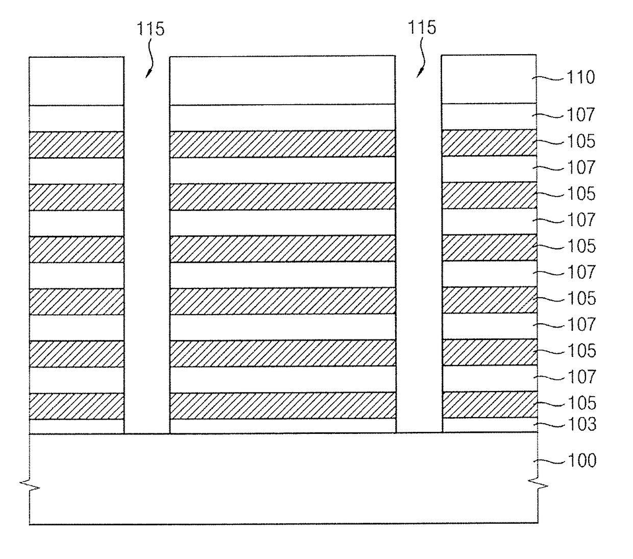
[0021]Exemplary embodiments of the present inventive concept will be described below in more detail with reference to the accompanying drawings. In this regard, the exemplary embodiments may have different forms and should not be construed as being limited to the exemplary embodiments of the present inventive concept described herein. Like reference numerals may refer to like elements throughout the specification and drawings.

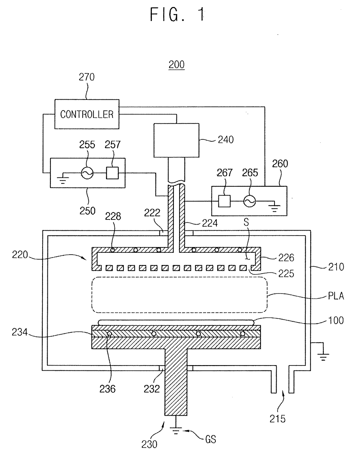
[0022]FIG. 1 is a cross sectional view illustrating a plasma etching apparatus in accordance with an exemplary embodiment of the present inventive concept.

[0023]Referring to FIG. 1, a plasma etching apparatus 200 in accordance with an exemplary embodiment of the present inventive concept may include a process chamber 210 in which an etching process using plasma is performed to a substrate 100. A source supplier 220 may be positioned at an upper portion of the process chamber 210 and may supply source gases for the etching process into the process chamber 210. A...


PUM


Abstract

Disclosed are a plasma etching apparatus and a method of manufacturing semiconductor devices using the same. The plasma etching apparatus includes a process chamber. A source supplier is positioned at an upper portion of the process chamber. The source supplier is configured to supply source gases for an etching process. A substrate holder is positioned at a lower portion of the process chamber opposite to the source supplier. The substrate holder is configured to support a substrate. A first power source is configured to apply a high frequency power to capacitively couple the source gases into a capacitively coupled plasma (CCP) in the process chamber. A second power source is configured to apply a low frequency pulse power at a low duty ratio of less than or equal to about 0.5:1. The low frequency pulse power is configured to guide the CCP toward the substrate supported by the substrate holder.

Description

CROSS-REFERENCE TO RELATED APPLICATION[0001]This application claims priority under 35 U.S.C §119 to Korean Patent Application No. 10-2016-0104203 filed on Aug. 17, 2016 in the Korean Intellectual Property Office, the disclosure of which is incorporated by reference herein in its entirety.1. Technical Field[0002]Exemplary embodiments of the present inventive concept relate to a plasma etching apparatus and a method of manufacturing a semiconductor device using the same.2. Discussion of Related Art[0003]Semiconductor devices may be high integration and high performance devices. An aspect ratio of fine patterns of semiconductor devices may be relatively high. The high aspect ratio of the pattern structure may result in various etch depth loadings such as a poor etching rate, an insufficient etching selectivity and various distortions of the fine pattern.[0004]Thus, high energy ions of etching gases may reach bottom of a contact hole or a via hole in fine pattern structures having the h...

Claims


Application Information

Patent Timeline
Patent Type & Authority Applications(United States)
IPC IPC(8): H01L21/3065H01L21/67H01L21/311H01J37/32
CPCH01L21/3065H01L21/67069H01J2237/334H01J37/321H01J37/32715H01L21/31116H01J37/32091H01J37/32146H01J37/32165H01J2237/3347H01J37/32128H01J37/32174H01L21/32136
Inventor PARK, MIN-JOONKIM, TAE-HWALEE, JAE-HYUNKWON, SANG-DONG
Owner SAMSUNG ELECTRONICS CO LTD
Learn More