
Driving circuit of surface light source and method of driving the same

Inactive Publication Date: 2008-05-08
MATHBRIGHT TECH
View PDF6 Cites 2 Cited by
  • Summary
  • Abstract
  • Description
  • Claims
  • Application Information

AI Technical Summary

Benefits of technology

[0023]An object of the present invention is to provide a driving circuit of a surface light source which is suitable for decreasing the luminance-stabilization period of time and improving the low-temperature starting properties by optimizing a starting voltage and current, and a method of driving the same.
[0030]Also, a duty ratio is relatively low if the current applied to the surface light source is high, and the duty ratio is relatively high if the current applied to the surface light source is low, to lower the power consumption.

Problems solved by technology

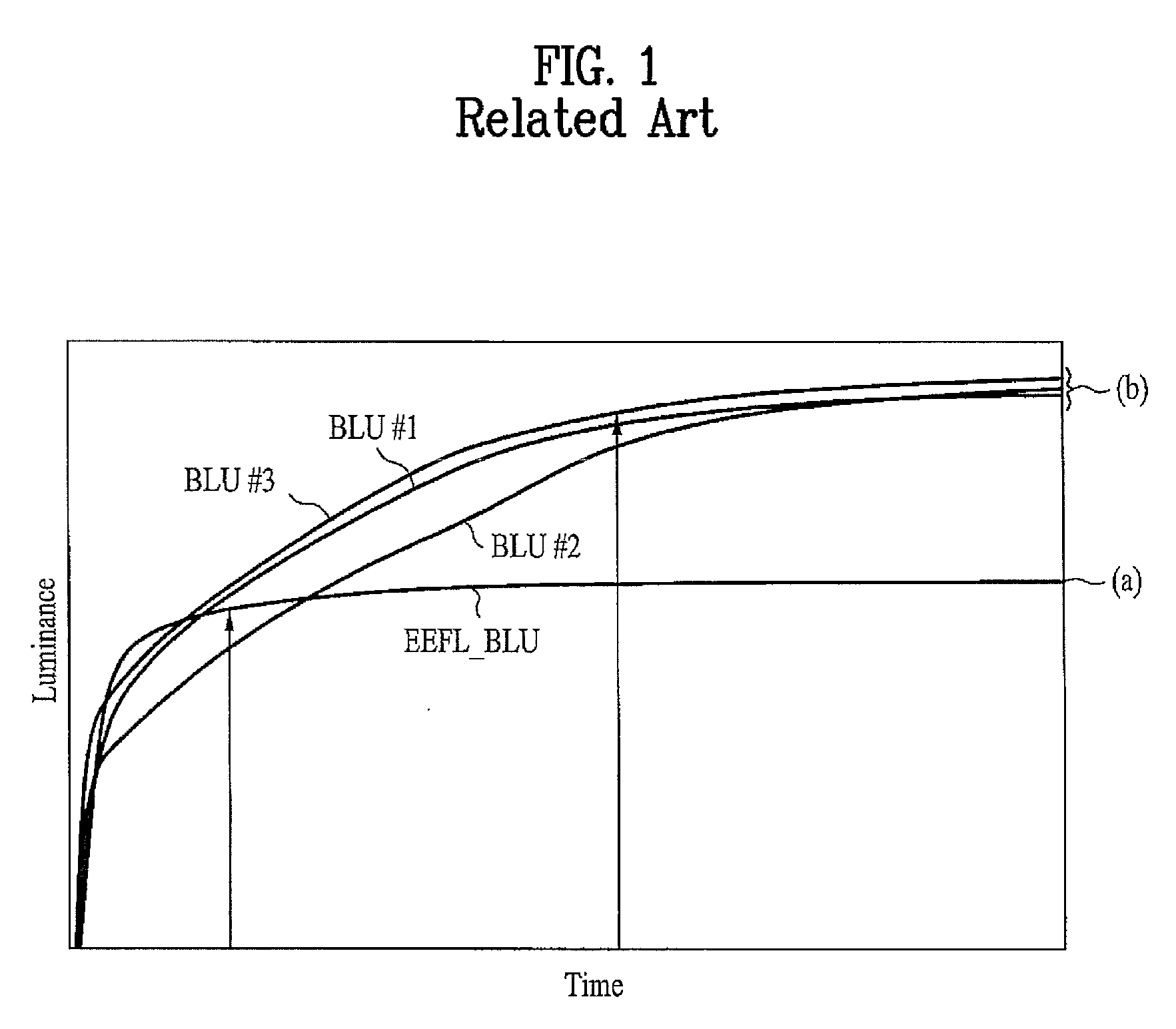
Unless the time period to stabilize the luminance of the FFL becomes shorter, it is difficult to apply the FFL to the backlight of the LCD device.
If the FFL using Hg gas is operated in the low-temperature surroundings, it spends a long time to activate Hg gas.
Also, since the flat fluorescent lamp has a large-sized cross section and also includes a plurality of channels, there is high possibility of ununiform discharge.
If a winding ratio is increased in primary and secondary windings of a transformer to supply the proper voltage and current (raising the voltage and current), the efficiency of driving circuit is deteriorated.
In this case, unless the voltage and current are slowly decreased by preset periods of time, the flickering and the rapid decrease of luminance may occur.

Method used


Image

  • Driving circuit of surface light source and method of driving the same
  • Driving circuit of surface light source and method of driving the same
  • Driving circuit of surface light source and method of driving the same

Examples


first embodiment

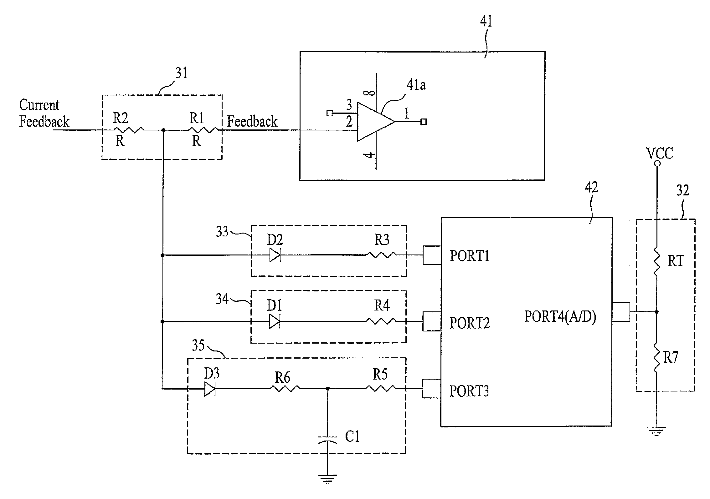
[0045]FIG. 4 is a schematic view of illustrating a driving circuit of a surface light source according to the present invention.

[0046]As shown in FIG. 4, the driving circuit of the surface light source according to the first embodiment of the present invention is comprised of a divider 31; an inverter controller 41; a temperature sensor 32; a first current breaker 35; a second current breaker 34; a third current breaker 35; and a driving-condition determining controller 42. At this time, the divider 31 includes resistors (R1, R2) to divide a current supplied to the surface light source by feedback. Then, the inverter controller 41 feedbacks the current supplied to the surface light source through the divider 31; compares the feedback current with a reference current value to thereby control the current applied to the surface light source. Also, the temperature sensor 32 includes a temperature sensing part (thermistor, RT) and a resistor (R7), thereby sensing the temperature in the c...

second embodiment

[0088]FIG. 9 is a schematic view of illustrating a driving circuit of a surface light source according to the present invention.

[0089]As shown in FIG. 9, the driving circuit of the surface light source according to the second embodiment of the present invention is comprised of a divider 31; an inverter controller 41; a temperature sensor 32; a first current breaker 33; a second current breaker 34; a third current breaker 35; and a driving-condition determining controller 42. At this time, the divider 31 includes resistors (R1, R2) to divide a current supplied to the surface light source by feedback. Then, the inverter controller 41 feedbacks the current supplied to the surface light source through the divider 31; and generates a driving pulse to control the current applied to the surface light source by comparing the feedback current with a reference current value. Also, the temperature sensor 32 includes a temperature sensing part (thermistor, RT) and a resistor (R7), thereby sensi...


PUM


Abstract

A driving circuit of a surface light source and a method of driving the same are disclosed, which is suitable for decreasing the luminance-stabilization period of time and improving the low-temperature starting properties by optimizing a starting voltage and current, the driving circuit comprising an inverter controller which feedbacks a current supplied to the surface light source, and compares the feedback current to a preset reference value, to control the current supplied to the surface light source; a temperature sensor which senses an operation temperature of the surface light source; and a driving-condition determining controller which determines operation modes of the surface light source on the basis of the temperature sensed in the temperature sensor, and varies the feedback current inputted to the inverter controller according to the operation modes of the surface light source.

Description

[0001]This application claims the benefit of Korean Patent Application No.10-2006-0109924 filed on Nov. 8, 2006, which is hereby incorporated by reference as if fully set forth herein.BACKGROUND OF THE INVENTION[0002]1. Field of the Invention[0003]The present invention relates to a driving circuit of a surface light source which is suitable for decreasing the luminance-stabilization period of time and improving the low-temperature starting properties by optimizing a starting voltage and current, and a method of driving the same.[0004]2. Discussion of the Related Art[0005]With the recent development in many kinds of light source, the wide application of the light sources has been accelerated in various fields, for example, illuminating fields, information industrial fields, and image-displaying industrial fields.[0006]The light source is largely classified into a one-dimensional light source including an optical distribution formed in shape of a dot; a two-dimensional light source in...

Claims


Application Information

Patent Timeline
IPC IPC(8): H05B37/02H05B44/00
CPCH05B41/386
Inventor HUR, JEONG WOOKLEE, HWAN WOONG
Owner MATHBRIGHT TECH
Learn More