
Integrated polarimeter in an optical line system

a polarimeter and optical line technology, applied in the field of fiber optic systems and methods, can solve the problems of optical line systems suffering new degrees of susceptibility to transients, errors, loss of framing, and unpredictability of sop transient sources in the fiber

Active Publication Date: 2017-12-14
CIENA
View PDF3 Cites 13 Cited by
  • Summary
  • Abstract
  • Description
  • Claims
  • Application Information

AI Technical Summary

Benefits of technology

The patent describes a polarimeter system integrated into an optical line system that can measure the state of polarization (SOP) of input light. The system includes a transmitter and a receiver, with a wavelength of the polarization probe signal that operates in-service with traffic-bearing channels on the output port. The system can be located at a first or second node in the optical line system and can include various optical components such as a PM coupler, PBSs, and detectors to measure the SOP. The system can operate continuously to collect SOP data and detect fast SOP transients. The technical effect of the system is to provide a tool for measuring SOP in real-time in an optical line system, which can help to improve the performance and stability of the system.

Problems solved by technology

With these advanced techniques, optical line systems suffer new degrees of susceptibility to transients on a time varying optical channel, including polarization transients, etc.
Coherent optical line systems are configured to track SOP changes as part of normal operation, but when quick SOP transients occur, these can be outside the tracking ability, leading to errors, loss of framing, etc.
Usually, SOP transient sources behave unpredictably and from unknown locations in the fiber.
SOP transients can be particularly problematic with coherent transmission, and especially difficult to localize / isolate given their nature in general.
Further, conventional polarimeters rely on free space optics which is not amenable to integration with fiber components (i.e., non-free space optics).
Conventional polarimeters require special design of bulk free space optics components and / or special coupling functions of an optical fiber leading to costly and bulky implementations.
Finally, conventional polarimeters are cost prohibitive for optical line system applications as well as complex providing vast more information than necessary for such optical line system applications, i.e., only SOP tracking is required to monitor the health of an optical fiber.

Method used


Image

  • Integrated polarimeter in an optical line system
  • Integrated polarimeter in an optical line system
  • Integrated polarimeter in an optical line system

Examples


Embodiment Construction

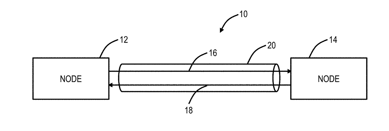
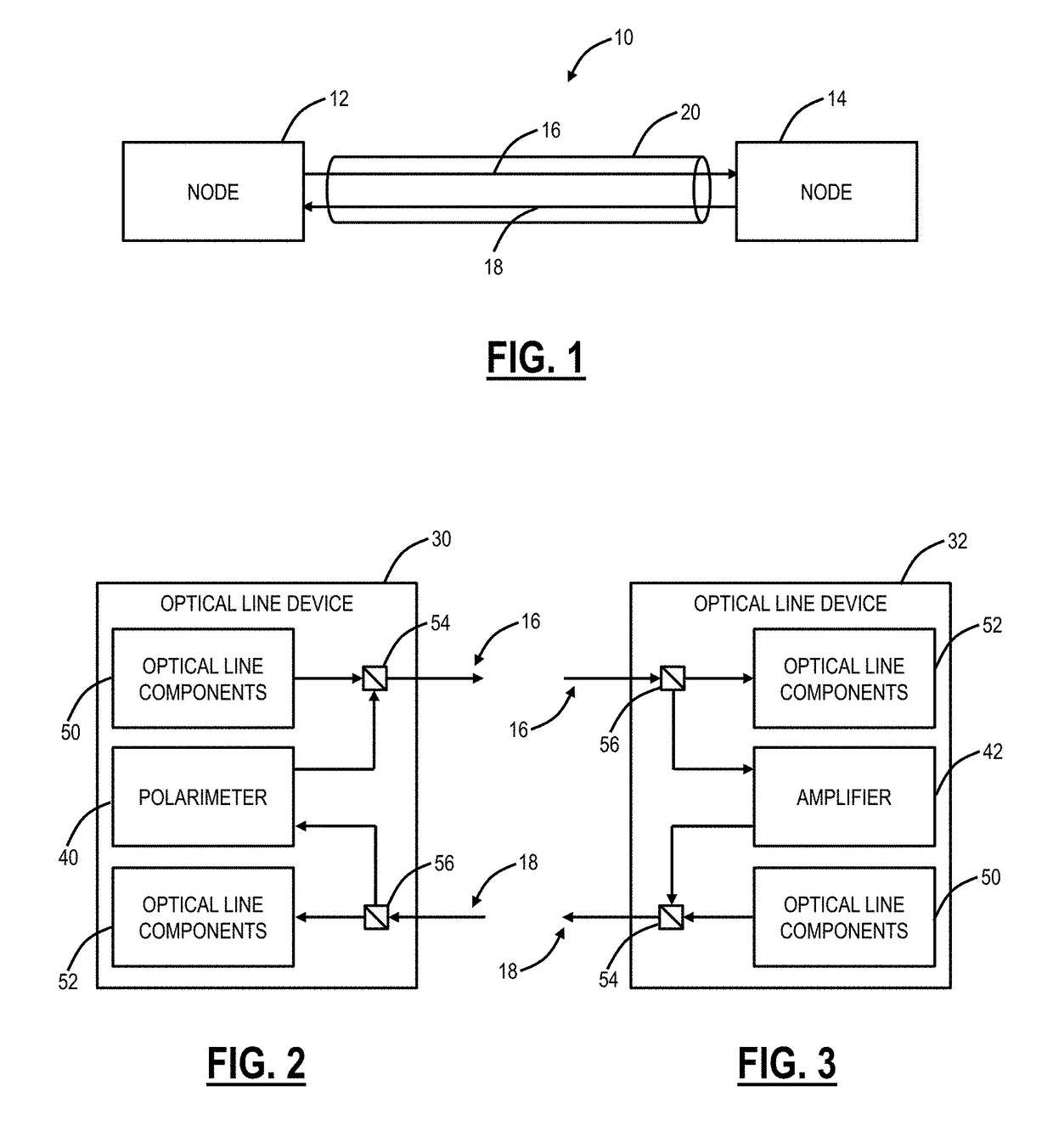
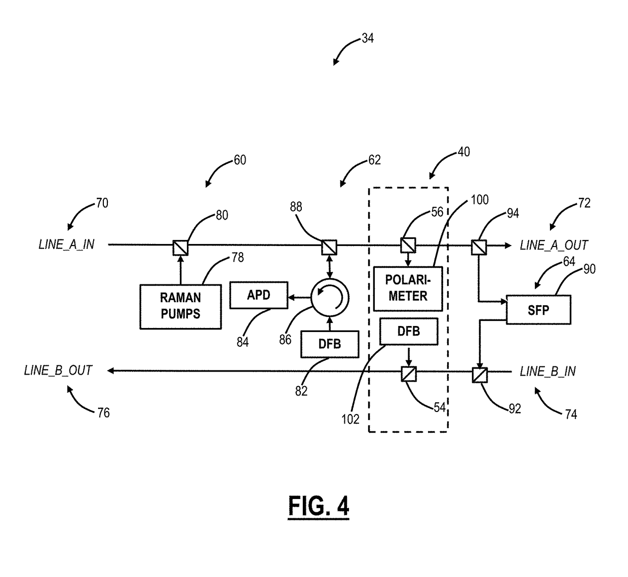
[0026]Again, in various exemplary embodiments, the present disclosure relates to an integrated polarimeter in an optical line system. The integrated polarimeter provides the functionality needed in optical line applications including detection of SOP transients, localization of the SOP transients to either an approximate distance or a span, overall health monitoring of the optical fiber, and the like. The integrated polarimeter is designed with “off-the-shelf” passive fiber optic components, lending itself to integration with existing components in the optical line system, such as in a line card, line module, pluggable module, hardware device, or the like. The integrated polarimeter includes a source laser and various exemplary embodiments for a detector based on Polarization Maintaining (PM) couplers and fibers, polarizers, and Polarization Beam Splitters (PBSs) coupled to detectors. Accordingly, the integrated polarimeter can collect real-time SOP transient data over individual sp...


PUM


Abstract

A polarimeter system integrated into an optical line system includes a transmitter coupled to a transmit filter communicatively coupled to an output port in an optical line device, wherein the transmitter is configured to generate a polarization probe signal, and wherein a wavelength of the polarization probe signal is configured to operate in-service with traffic-bearing channels on the output port; and a polarimeter receiver coupled to a receive filter communicatively coupled to an input port in the optical line device, wherein the polarimeter receiver is configured to vary arrangement of input light from the filter and to measure various outputs of the varied arrangement to derive measurement of State of Polarization (SOP) of the input light.

Description

FIELD OF THE DISCLOSURE[0001]The present disclosure generally relates to fiber optic systems and methods. More particularly, the present disclosure relates to an integrated polarimeter in an optical line system.BACKGROUND OF THE DISCLOSURE[0002]As bandwidth continues to grow, capacity is being stretched in fiber optic networks (Wavelength Division Multiplexing (WDM), optical line systems, etc.). Various advanced techniques are used to provide additional bandwidth including advanced coherent modulation techniques, polarization multiplexing, flexible grid spacing, and the like in optical line systems. With these advanced techniques, optical line systems suffer new degrees of susceptibility to transients on a time varying optical channel, including polarization transients, etc. As described herein, an State of Polarization (SOP) transient source causes an SOP transient which is anything that causes quick changes in the SOP of signals on an optical fiber. Coherent optical line systems a...

Claims


Application Information

Patent Timeline
IPC IPC(8): G01J4/00H01S3/00G02B6/42
CPCG01J4/00G02B6/4216H01S3/0007H04B10/0775H04B2210/078
Inventor PEI, YINQINGARCHAMBAULT, JEAN-LUCBOERTJES, DAVID W.DOUCET, DAVID R.
Owner CIENA
Learn More