
Ice blasting apparatus and trimming method for film insert molding

a technology of ice blasting apparatus and film insert molding, which is applied in the field of ice blasting process technology, can solve the problems of unfavorable stocking, unfavorable stocking, and considerably difficult to implement stable production and supply of ice pellets at low cost from a practical point, so as to achieve fast trimming and ensure the effect of safety and reliability, stably and accurately supplying ice slurry

Inactive Publication Date: 2006-05-09
TOSHIBA MASCH CO LTD
View PDF8 Cites 68 Cited by
  • Summary
  • Abstract
  • Description
  • Claims
  • Application Information

AI Technical Summary

Benefits of technology

[0014]It is an object of the present invention to provide a blast apparatus capable of enduring continuous operation for long time and stably and accurately supplying ice slurry of an exact concentration, and a method allowing speedy trimming with safety and reliability without any damage to a surface of a film material when a unnecessary portion of the film material is removed from a film insert molding.

Problems solved by technology

Because of a great problem involved in commercialization, ice blasting falls short of completely replacing conventional dry blasting and wet blasting using abrasives.
Hence, although it goes without saying that definitive methods for producing and supplying ice pellets are of significant importance, there is a considerably difficult problem in implementing the stable producing and supplying of the ice pellets at low cost from a practical point of view, aside from the theory.
In other words, unlike usual abrasives, ice pellets have the unstable property of being incapable of keeping their form at room temperature, making stocking unfeasible.
A high technique is necessary to continue to stably and continuously produce and supply ice pellets of the form best suited for the emitted material, which in turn requires high costs.
If the concentrations are not properly controlled, there is not even the remotest possibility of yielding satisfactory result of the blasting process.
Up to now, however, it has been virtually impossible to find an ice blasting apparatus using such an ice making device and an ice mixing tank, which has been perfected so as to be capable of giving a high degree of satisfaction from all aspects.
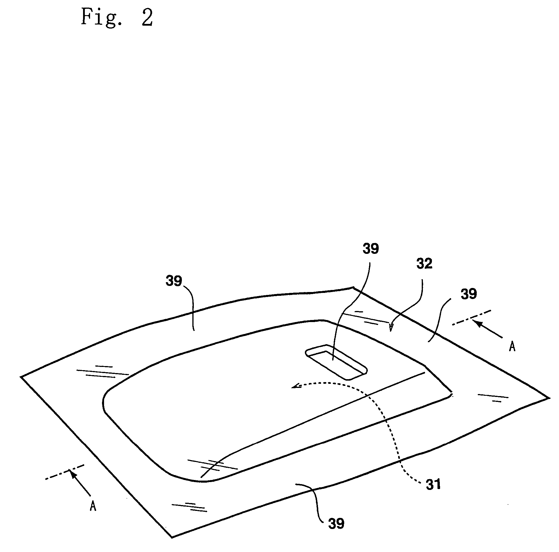
Further, the film material 32 is soft and unsteady.
Time and effort are naturally required, which in turn makes bulk handling in a short time impossible.
Many defective products are produced, making shipment impossible.
However, this attempt has not yet been successfully put into actual use because of the high cost required for facilities and the overstressing of the resin molding 31.
However, an abrasive is used as the emitted material in the dry blasting and the wet blasting.
Hence, it is inevitable that the surface of the film material 32 is damaged and roughened to varying degrees when the abrasive comes into collision with the surface of the film material 32.
However, in the case of relatively high quality products such as an interior vehicle component composed of the resin molding 31 and a woodgrain-pattern printed film or a very smooth, glossy film adhering integrally to the surface of the resin molding 31, a roughened surface of the film material is undesirable.
As described hitherto, a blasting process is not able to be used as the finishing process for various resin moldings, particularly, a film insert molding, resulting in hindrance to any improvement in working efficiency.

Method used


Image

  • Ice blasting apparatus and trimming method for film insert molding
  • Ice blasting apparatus and trimming method for film insert molding
  • Ice blasting apparatus and trimming method for film insert molding

Examples


Embodiment Construction

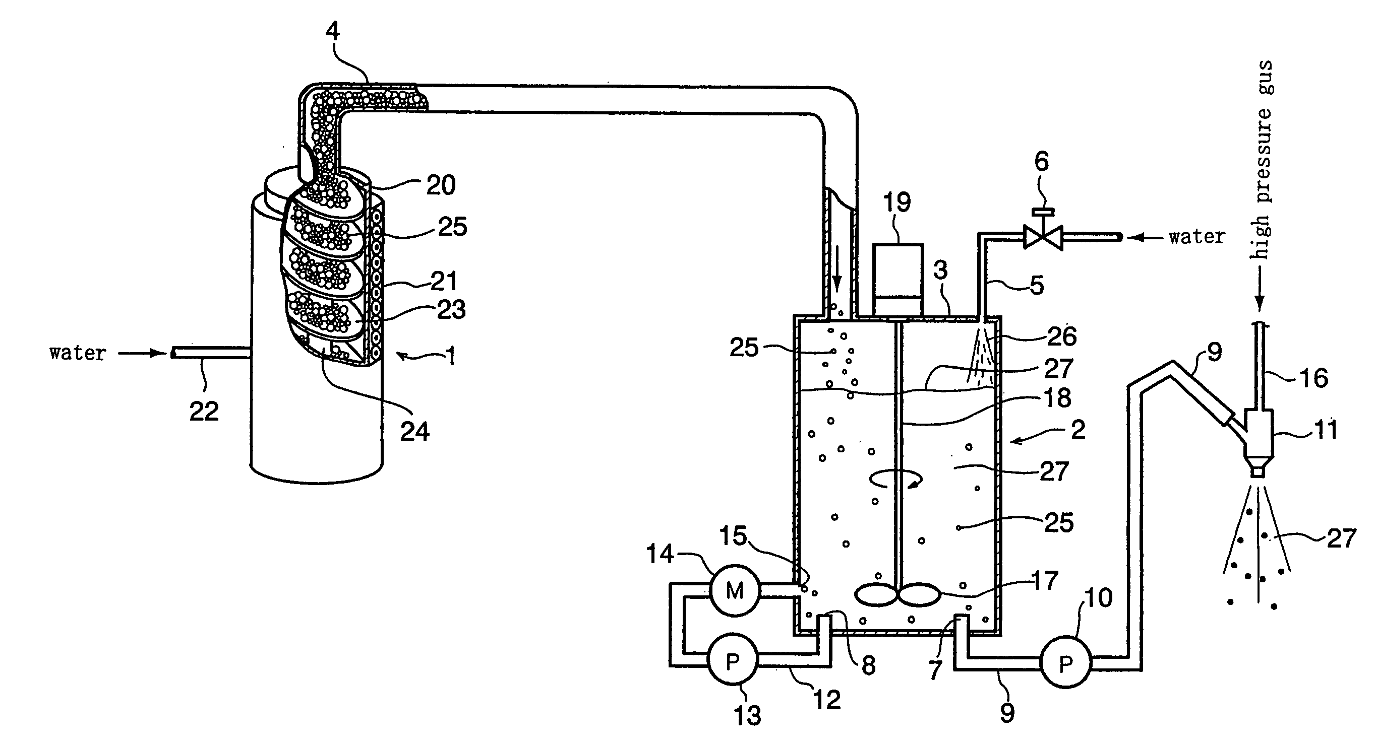
[0024]A preferred embodiment of an ice blasting apparatus according to the present invention will be described below with reference to the accompanying drawings. FIG. 1 shows an ice making device 1 and an ice mixing tank 2. Reference numeral 20 in FIG. 1 denotes a cylindrical-shaped freezing casing forming a main part of the ice making device 1. A freezing evaporator 21 in which a refrigerating catalyst is circulated is attached on the outer periphery face of the freezing casing 20. Water which is raw material of ice is supplied into the freezing casing 20 through a water feed pipe 22. An auger screw 24 is axially supported inside the freezing casing 20. The auger screw 24 has a cutting blade 23 of a helical shape with an outer diameter slightly smaller than the inner diameter of the freezing casing 20. The auger screw 24 is rotationally moved by a drive source (not shown), so that the cutting blade 23 successively shaves off the ice that is frozen on the inner wall face of the free...


PUM

PropertyMeasurementUnit
pressureaaaaaaaaaa
speedaaaaaaaaaa
air pressureaaaaaaaaaa

Abstract

An ice blasting apparatus comprises: an ice making device operating a cutting blade to shave off ice freezing on an inner wall of the freezing casing and continuously discharges the shaved ice as flake-shaped ice pellets; an ice mixing tank mixing the ice pellets and water and maintaining the resulting ice slurry at a predetermined concentration with a concentration sensor; and a blast gun blasting the ice slurry. A trimming method is performed on a film insert molding with a film material adhering to a face of a resin molding and extending beyond a periphery edge of the resin molding. A blast gun facing the face with the film adhering to it blasts ice slurry of a required concentration toward the vicinity of the periphery edge of the resin molding to remove the unnecessary portion of the film material extending beyond the periphery edge of the resin molding.

Description

BACKGROUND OF THE INVENTION[0001]1. Field of the Invention[0002]This invention relates to a technique associated with an ice blasting process, more particularly, an apparatus for producing and ejecting ice pellets, and a method of using ice blasting to perform the finishing process on film-insert injection moldings.[0003]2. Description of the Related Art[0004]Ice blasting apparatus using slurry that includes a mixture of ice pellets and water as an emitted material does not use any abrasive, and therefore does not cause any damage to articles undergoing the blasting process. Further, the ice blasting apparatus has no abrasive residues left after the completion of the blasting process and thus is in no need of a disposal process for liquid wastes that includes an abrasive. For these reasons, such ice blasting apparatuses have captured much of the spotlight as next-generation blasting apparatuses, and are being assiduously developed for eventual commercialization.[0005]Ice blasting is...

Claims


Application Information

Patent Timeline
Patent Type & Authority Patents(United States)
IPC IPC(8): B24C1/04B24C1/00B29C37/02B29C45/00B29C45/14
CPCB24C1/003B24C1/083B24C1/086B29C37/02B29C2059/027B29C45/14B29C2045/0058B29C2045/0077B29C45/0055
Inventor MAKINO, SHINICHIKOJIMA, NAOKATSU
Owner TOSHIBA MASCH CO LTD
Learn More