
Digital controller for a MEMS gyroscope

a digital controller and microelectromechanical technology, applied in the direction of code conversion, turn-sensitive devices, instruments, etc., can solve the problems of inability to effectively create tuneable analog components, increased risk of parasitic elements, and inaccuracy of detection, so as to achieve accurate detection of angular velocity, reduce the risk of parasitic elements, and improve the effect of detection and compensation capability

Active Publication Date: 2017-11-16
MURATA MFG CO LTD
View PDF0 Cites 36 Cited by
  • Summary
  • Abstract
  • Description
  • Claims
  • Application Information

AI Technical Summary

Benefits of technology

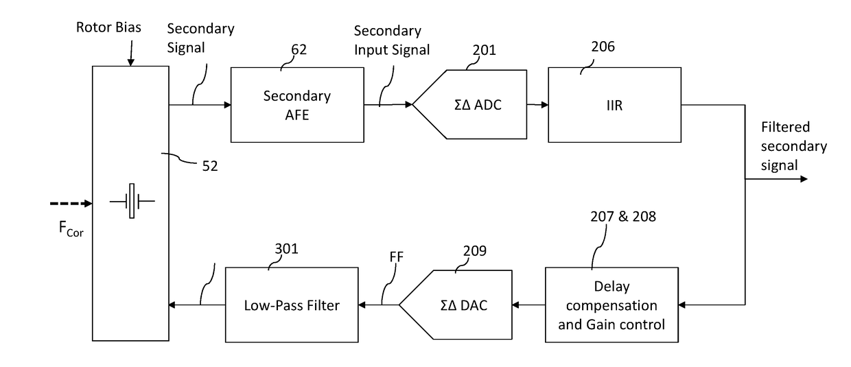
The invention provides a digital control circuitry for a MEMS device that has the advantage of precise detection of angular velocity, good detection and compensation of non-idealities, low sensitivity to variation of component parameters, and good noise tolerance. The use of a digital primary loop circuitry provides a reliable oscillating signal, which is in set frequency and phase relation with the signal of the primary oscillation. The digital circuitry uses low clock frequency in the digital parts without compromising the accuracy of the MEMS device, reducing cost of the circuitry and power consumption. The use of a single digital filter in the primary loop provides several functionalities improving performance of the entire circuitry in a very cost efficient way. The same digital filter in the secondary loop provides several functionalities with relatively small amount of processing and circuit area. The provided patent text demonstrates the power-saving and cost-effectiveness of the invention.

Problems solved by technology

Use of analog signal processing in control loops of a MEMS gyroscope causes several challenges and problems.
Analog components are highly sensitive to variations in component parameters, which may cause inaccuracy to detection.
Further, it is difficult to create tuneable analog components cost and area effectively.
Adding tunability into analog components typically increases area required for the components which again causes increase in risk for leakage currents and parasitic elements.
Calibration of a MEMS gyroscope with analog signal processing is a difficult task, and even slight deviation from the optimal calibration cause inaccuracy in detection of the angular rate.
Using analog components for implementing circuitry capable of handling big time constants is difficult, although such may be needed for noise limiting purposes.
For example, area required for a suitable analog circuitry may be unpractically large.
High frequencies increase power consumption and also required circuitry area required by the digital circuitry.
Although the digital PLL is basically useful solution for introducing the necessary 90 degree phase delay for the primary signal for generating the actuation force, implementing a DDS is a very complicated and area consuming task.

Method used


Image

  • Digital controller for a MEMS gyroscope
  • Digital controller for a MEMS gyroscope
  • Digital controller for a MEMS gyroscope

Examples


first embodiment

[0116]The implementation of FIG. 3 with a DF (106) in the digital primary loop may require high gain during system start-up, because the drive signal is generated directly from the detected primary signal and this signal is initially weak during start-up when the motion of the primary mass has small amplitude. In order to allow the DF (106) to have a higher gain in order to fulfill required start-up amplification needs, an amplitude limiting circuitry AL (107) is introduced in this first embodiment for limiting amplitude of the digitized primary signal when sufficient amplitude has been achieved during start-up and naturally also during normal operation of the device, so that amplitude of the digitized primary signal is maintained on linear range of the circuitry. Such amplitude limiting circuitry AL (107) may comprise for example a logarithmic scaler or a simple right shifting element for data bits, which limits the amplitude of the digitized primary signal provided at the output o...

second embodiment

[0121]In another embodiment illustrated in FIG. 5, the multiplexer circuitry MUX (109) is placed in the digital primary loop (100) only after the digital summing element (105) and before the first DAC (110). Similarly to the earlier start-up multiplexer embodiment, the purpose of the multiplexer circuitry (109) is to enable provision of a start-up impulse towards the drive loop for start-up purposes. In this second embodiment, the start-up impulse is fed first towards the primary analog back end and the primary mass, causing the primary mass to start moving, which movements reflects in the primary input signal. This alternative may become feasible if the Q-value of the DF (106) is e.g. below unity, in which case it would attenuate the power of the impulse at the resonance frequency in the case of FIG. 4.

[0122]Although two specific examples have been disclosed herein, other possible locations in the digital primary loop (100) may be applicable for the multiplexer circuitry MUX (109) ...


PUM


Abstract

A digital control circuitry for a MEMS gyroscope is provided. The digital control circuitry comprises a digital primary loop circuitry configured to process a digitized primary signal, a digital secondary loop circuitry configured to process a digitized secondary signal and a digital phase shifting filter circuitry configured to generate two phase shifted demodulation signals from the digitized primary signal. The digital secondary loop is configured to demodulate the digitized secondary signal using the two phase shifted demodulation signals.

Description

BACKGROUNDField[0001]The present invention relates to micro-electro-mechanical (MEMS) gyroscopes and especially to a digital controller for a micro-electro-mechanical gyroscope. The present invention further relates to a MEMS gyroscope and more particularly to a MEMS gyroscope comprising a digital controller circuitry.[0002]Motion can be considered to have six degrees of freedom: translations in three orthogonal directions and rotations around three orthogonal axes. The latter three may be measured by an angular rate sensor, also known as a gyroscope. MEMS gyroscopes use the Coriolis Effect to measure the angular rate. When a mass is driven in one direction and rotational angular velocity is applied about axis orthogonal to driven axis, the mass experiences a force in orthogonal direction with respect to both driven and rotated axes as a result of the Coriolis force. The Coriolis force is dependent on the speed of movement of the mass. The resulting physical displacement caused by t...

Claims


Application Information

Patent Timeline
IPC IPC(8): G01C19/5726H03H17/02H03G3/20H03D7/00H03M3/00
CPCG01C19/5726H03H17/0248H03D7/00H03G3/20H03M3/458H03M3/436H03D2200/0054H03D2200/0082H03D2200/005H03H2218/04G01C19/5649G01C19/5656G01C19/5776B81B7/02G01C19/56B81B2201/0242
Inventor COLLIN, RAULIWJUGA, KONSTAAALTONEN, LASSE
Owner MURATA MFG CO LTD
Learn More