
Diffuse reflection material, diffuse reflection layer, wavelength conversion device and light source system

a technology of diffuse reflection and diffuse material, which is applied in the direction of diffusing elements, lighting and heating apparatus, instruments, etc., can solve the problems of nigrescence of mirror silver/aluminum, adverse to and thermal resistance, so as to improve the thermostability of wavelength conversion devices and improve the reflective index of diffuse reflection materials

Active Publication Date: 2017-11-09
APPOTRONICS CORP LTD
View PDF0 Cites 7 Cited by
  • Summary
  • Abstract
  • Description
  • Claims
  • Application Information

AI Technical Summary

Benefits of technology

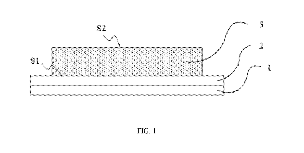
The present patent provides a solution to improve the reflective index and thermostability of a diffuse reflection material and a wavelength conversion device. The solution involves using high reflection scattering particles with a whiteness greater than 90, high refraction scattering particles, and high thermal conductivity scattering particles as raw materials. By taking advantage of the effect of thinning the reflective layer mainly by the high refraction scattering particles and enhancing the heat conduction effect in the diffuse reflection layer by the high thermal conductivity scattering particles, the diffuse reflective index is maintained while reducing the thickness of the diffuse reflection layer, resulting in improved luminous efficiency and thermostability of the wavelength conversion device when excited with a high power laser.

Problems solved by technology

With the increase in the light source power of lasers, mirror silver / aluminum suffers from an increasingly severe problem of nigrescence due to oxidation at a high temperature.
However, with respect to a thickness of hundreds of nanometer of the medium protection layer of a mirror silver surface, such film thickness will increase the conduction paths of heat generated by the fluorescent layer, thereby leading to a higher thermal resistance, which is adverse to luminous thermostability of the wavelength conversion device.
How to take account of both luminous efficiency and thermostability of a wavelength conversion device has become a new issue for the research and development personnel.
However, wavelength conversion devices formed by this material lack in luminous stability when excited with a laser at a high power density.

Method used


Image

  • Diffuse reflection material, diffuse reflection layer, wavelength conversion device and light source system
  • Diffuse reflection material, diffuse reflection layer, wavelength conversion device and light source system

Examples


example 1

[0050]Raw materials: 0.1 g of aluminum oxide (spherical, with a particle diameter of 0.2 μm), 0.6 g of titanium oxide (spherical, with a particle diameter of 0.2 μm), 0.4 g of boron nitride (flat, with a length in the flat direction of 0.7 μm, and a length in the thickness direction of 0.02 μm), and 1 g of glass powder.

[0051]Preparation method: aluminum oxide, titanium dioxide, and boron nitride as well as the glass powder and 1 g of organic carrier (which was terpineol, butyl carbitol acetate, ethyl cellulose) were mixed to form a mixed material; the mixed material was blade coated onto an aluminum nitride substrate surface and sintered at 800° C.; and the steps of blade coating and sintering were repeated to form a diffuse reflection layer with a thickness of 30 μm, which was determined to have a reflective index of 92.4%.

example 2

[0052]Raw materials: 0.08 g of magnesium oxide (spherical, with a particle diameter of 0.3 μm), 0.7 g of zirconium oxide (spherical, with a particle diameter of 0.3 μm), 0.3 g of aluminum nitride (rod-like, with a length in the length direction of 1.0 μm, and a diameter length in the peripheral direction of 0.02 μm), and 1 g of glass powder.

[0053]Preparation method: the above magnesium oxide, zirconium oxide, and aluminum nitride as well as the glass powder and 1 g of organic carrier (which was a solution of PVA in water) were mixed to form a mixed material; the mixed material was blade coated onto a silicon nitride substrate surface and sintered at 600° C.; the steps of blade coating and sintering were repeated to form a diffuse reflection layer with a thickness of 30 μm, which was determined to have a reflective index of 90.8%.

example 3

[0054]Raw materials: 0.08 g of barium sulfate (spherical, with a particle diameter of 0.5 μm), 0.5 g of zinc oxide (spherical, with a particle diameter of 0.5 μm), 0.3 g of aluminum nitride (flat, with a length in the flat direction of 2.5 μm, and a length in the thickness direction of 0.1 μm), and 1 g of glass powder.

[0055]Preparation method: the above barium sulfate, zinc oxide, and aluminum nitride as well as the glass powder and 2.5 g of organic carrier (which was formed by dissolving ethyl cellulose into a mixed solvent of terpineol and acetyl tributyl citrate) were mixed to form a mixed material; the mixed material was blade coated onto a boron nitride substrate surface and sintered at 1000° C.; and the steps of blade coating and sintering were repeated to form a diffuse reflection layer with a thickness of 30 μm, which was determined to have a reflective index of 91.3%.


PUM

PropertyMeasurementUnit
refractive indexaaaaaaaaaa
radiusaaaaaaaaaa
lengthaaaaaaaaaa

Abstract

A diffuse reflection material, a diffuse reflection layer, a wavelength conversion device, and a light source system are disclosed. The diffuse reflection material includes white scattering particles and an adhesive agent, where the whiteness of the white scattering particles is greater than 85, and the white scattering particles contain high reflection scattering particles with a whiteness of greater than 90, high refraction scattering particles with a refractive index of greater than or equal to 2.0, and high thermal conductivity scattering particles, where the high thermal conductivity scattering particles are boron nitrite and / or aluminum nitride particles, and the particle shape of the high thermal conductivity scattering particles is rod-like or flat. The reduction in the thickness of the diffuse reflection layer is realized while keeping a high reflectivity, thus causing the wavelength conversion device to have both a high light efficiency and high heat stability.

Description

BACKGROUNDTechnical Field[0001]The present disclosure relates to the field of optical energy sources, and in particular to a diffuse reflection material, diffuse reflection layer, a wavelength conversion device and a light source system.Description of the Related Art[0002]At present, the excitation of a high speed color wheel by blue light laser can effectively solve the heat quenching problem with a phosphor powder to realize a high-efficiency and low-cost laser display, and has gradually developed into one of the mainstream technologies of laser light sources. In this solution, the light sources include an excitation source and a wavelength conversion device, where the wavelength conversion device includes a reflective substrate and a phosphor powder sheet coated onto the reflective substrate, as well as a motor for driving rotation of the reflective substrate, to allow light spots formed on the phosphor powder sheet by exciting light from the excitation source to act on the phosp...

Claims


Application Information

Patent Timeline
Patent Type & Authority Applications(United States)
IPC IPC(8): G02B5/02C09K5/14C03C14/00C04B41/50C03C8/16F21V9/16C03C8/20C04B41/86
CPCG02B5/0242C09K5/14C03C8/20C03C14/004C03C2214/04C04B41/5022C04B41/86F21V9/16C03C2209/00C03C8/16G02B1/00F21V7/30F21V13/14C04B35/62222C04B35/63C04B2235/3217C04B2235/3232C04B2235/386
Inventor TIAN, ZIFENGXU, HULI, QIAN
Owner APPOTRONICS CORP LTD
Learn More