
Dynamic switching biosensor

a biosensor and dynamic switching technology, applied in the field of biochemical detection and monitoring, can solve the problems of slow response time of the sensor, signal and noise characteristics can change over time, and prolong the blocking time, and achieve high specificity, high off-rate, and high dynamic signals.

Active Publication Date: 2017-11-02
TECH UNIV EINDHOVEN
View PDF5 Cites 6 Cited by
  • Summary
  • Abstract
  • Description
  • Claims
  • Application Information

AI Technical Summary

Benefits of technology

The invention provides a biosensor with a molecular architecture that has high specificity and sensitivity, allowing for real-time calibration and improved statistics. The biosensor has a modular architecture that can be adapted for different analytes. The method for sensing an analyte involves detecting changes in distance and orientation between mediators and mediator-receptors using an optical or electrical sensor. The presence of the analyte is determined by a processor from the detected changes. The invention improves the accuracy and reliability of biosensing systems and can be used in various fields such as medical diagnostics and environmental monitoring.

Problems solved by technology

In-vivo monitoring is typically done using electrochemical sensors, but those are only suited for high-concentration analytes, e.g., glucose.
It remains a problem to detect low-concentration analytes with high specificity in a complex biological matrix (or a derivative thereof), e.g., in blood plasma, whole blood, skin interstitial fluid, gland fluid, tear fluid, mucus, mucous glands, saliva, cells, etc.
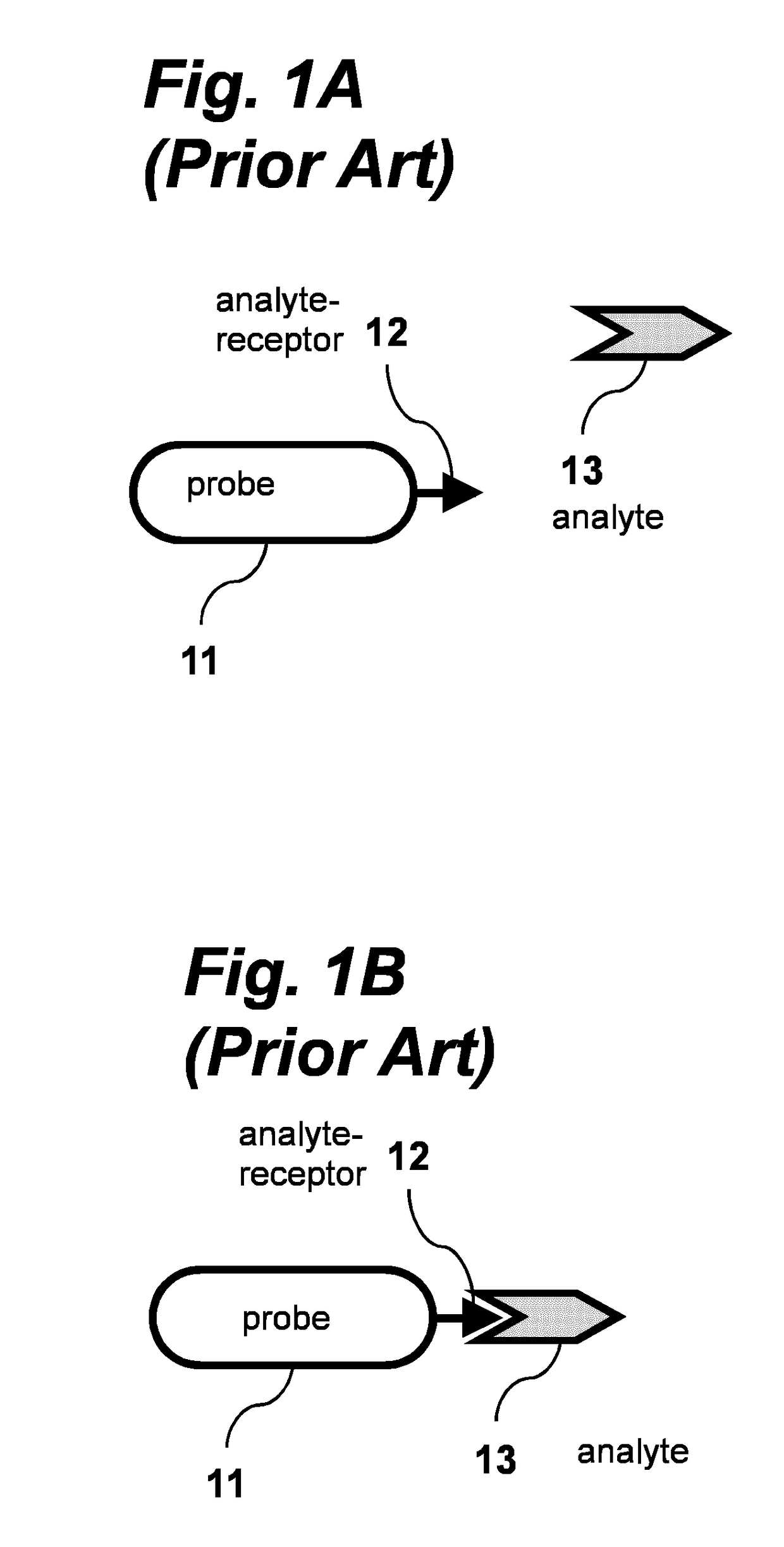
One problem of the biosensor in FIGS. 1A-B is that analytes are typically detected by using recognition molecules with strong binding affinities, such as, e.g., antibody-like molecules.
A problem is that low off-rates result in extended blocking times because the bound analyte occupies the receptor.
This will not only limit the statistics that can be gathered in a certain time-frame, but will also result in a slow response time of the sensor, which is problematic for real-time monitoring applications.
Another problem with the biosensor in FIGS. 1A-B is accuracy.
A difficulty is that signal and noise characteristics can change over time, e.g., due to variations in an optical excitation system (e.g., incident power), variations in an optical detection system (e.g., focal drift), variations in a probe property (e.g., due to temperature changes), variations in molecular properties on a probe (e.g., number of active molecules on the probe, mobility of signalling molecules on the probe surface), or variations of a property of the sample fluid (e.g., viscosity).
These variations are easily misinterpreted as being signals, which reduces the accuracy and reliability of the sensor.
Another problem is that detection of different analytes requires the use of different recognition molecules on the particle, and therefore the development of novel procedures to couple recognition molecules to the probe.

Method used


Image

  • Dynamic switching biosensor
  • Dynamic switching biosensor
  • Dynamic switching biosensor

Examples


Embodiment Construction

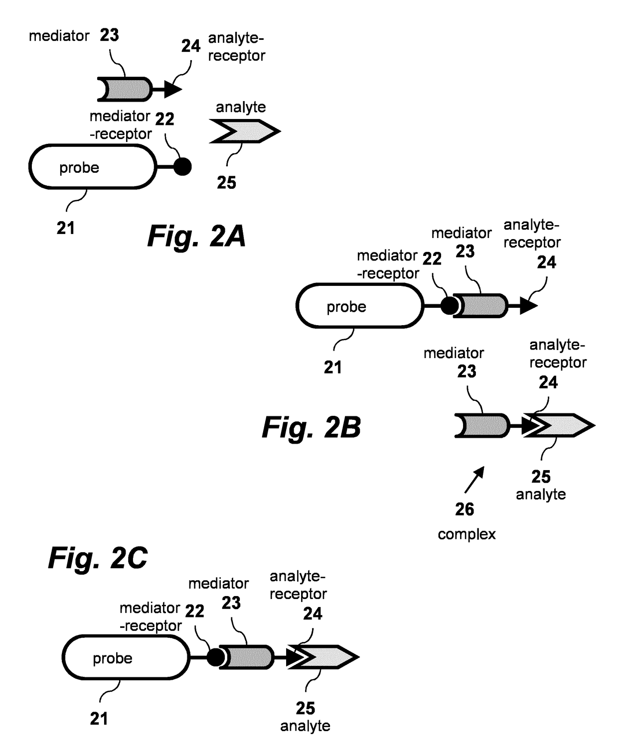
[0024]A biosensing technique using a non-tethered mediator according to one embodiment of the invention is schematically illustrated in FIGS. 2A-C.

[0025]As shown in FIG. 2A, biosensing probe 21 carries at least one mediator-receptor 22 on its surface. Mediator 23 is conjugated to at least one analyte-receptor 24, and is present in the environment of at least one probe 21. This configuration represents a probe 21 with a mediator-receptor 22 to which no mediator 23 is bound, and a mediator 23 to which no analyte 25 is bound. As shown in FIG. 2B, mediator 23 can bind to mediator-receptor 22. Alternatively mediator 23 can also bind to analyte 25 via analyte-receptor 24, forming complex 26. As shown in FIG. 2C, Mediator 23 can simultaneously bind both to mediator receptor 22 and to analyte 25.

[0026]The probe 21 is a biosensing element that can report binding events with single-object resolution, where the object is a molecule, a macromolecule, a nanoparticle, etc. The probe can be a mole...


PUM

PropertyMeasurementUnit
diameteraaaaaaaaaa
diameteraaaaaaaaaa
sizeaaaaaaaaaa

Abstract

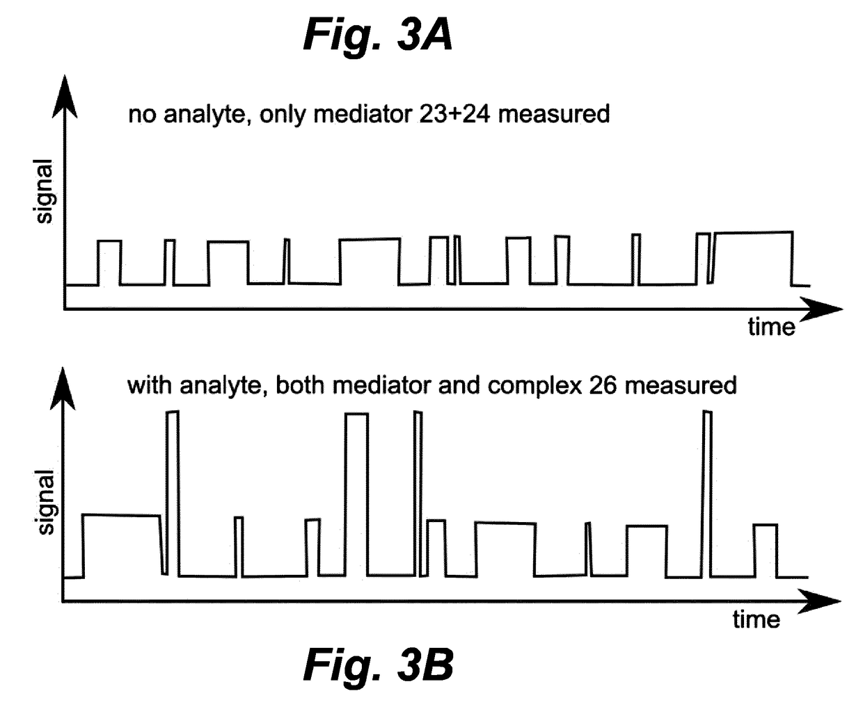
An analyte [25] in a matrix is sensed using a sensing device having a detection probe [21] conjugated to a mediator-receptor [22] that is not a binder for the analyte. The sensor device is provided with mediators [23] conjugated to analyte-receptors [24], where the mediators are selected to bind to the mediator-receptors, and where the analyte-receptors are selected to bind to the analyte. In some embodiments, the mediators are bound to the detection probe by a tether molecule, or tether molecule fragment, or tether domain. In other embodiments, the mediators are not bound to the detection probe. The presence of the analyte is detected by optically or electrically detecting changes of distance between the mediators and the mediator-receptor, indicative of association and / or dissociation events between mediators and mediator-receptor, the characteristics of which are affected by whether the analyte is bound to the analyte-receptor.

Description

FIELD OF THE INVENTION[0001]The present invention relates generally to biochemical detection and monitoring. More particularly, the invention relates to a biosensing device for the detection of analyte in fluid.BACKGROUND OF THE INVENTION[0002]In-vivo monitoring is typically done using electrochemical sensors, but those are only suited for high-concentration analytes, e.g., glucose. It remains a problem to detect low-concentration analytes with high specificity in a complex biological matrix (or a derivative thereof), e.g., in blood plasma, whole blood, skin interstitial fluid, gland fluid, tear fluid, mucus, mucous glands, saliva, cells, etc.[0003]A recent development is biosensors based on single-molecule detection principles, where the binding of an analyte molecule to a probe results in a detection signal with a digital characteristic, e.g., an analyte molecule is present or is not-present. Single-molecule detection has distinct advantages over ensemble-averaged techniques becau...

Claims


Application Information

Patent Timeline
Patent Type & Authority Applications(United States)
IPC IPC(8): G01N33/543C12Q1/68
CPCG01N33/54306C12Q1/6825G01N33/54373G01N33/54313G01N33/542G01N33/6872C12Q1/6816C12Q2565/107C12Q2565/133C12Q2565/607C12Q2565/628
Inventor PRINS, MENNO WILLEM JOSEZIJLSTRA, PETERBRUNSVELD, LUCAS
Owner TECH UNIV EINDHOVEN
Learn More