
Honeycomb structure, and manufacturing method of honeycomb structure

Active Publication Date: 2017-09-28
NGK INSULATORS LTD
View PDF4 Cites 0 Cited by
  • Summary
  • Abstract
  • Description
  • Claims
  • Application Information

AI Technical Summary

Benefits of technology

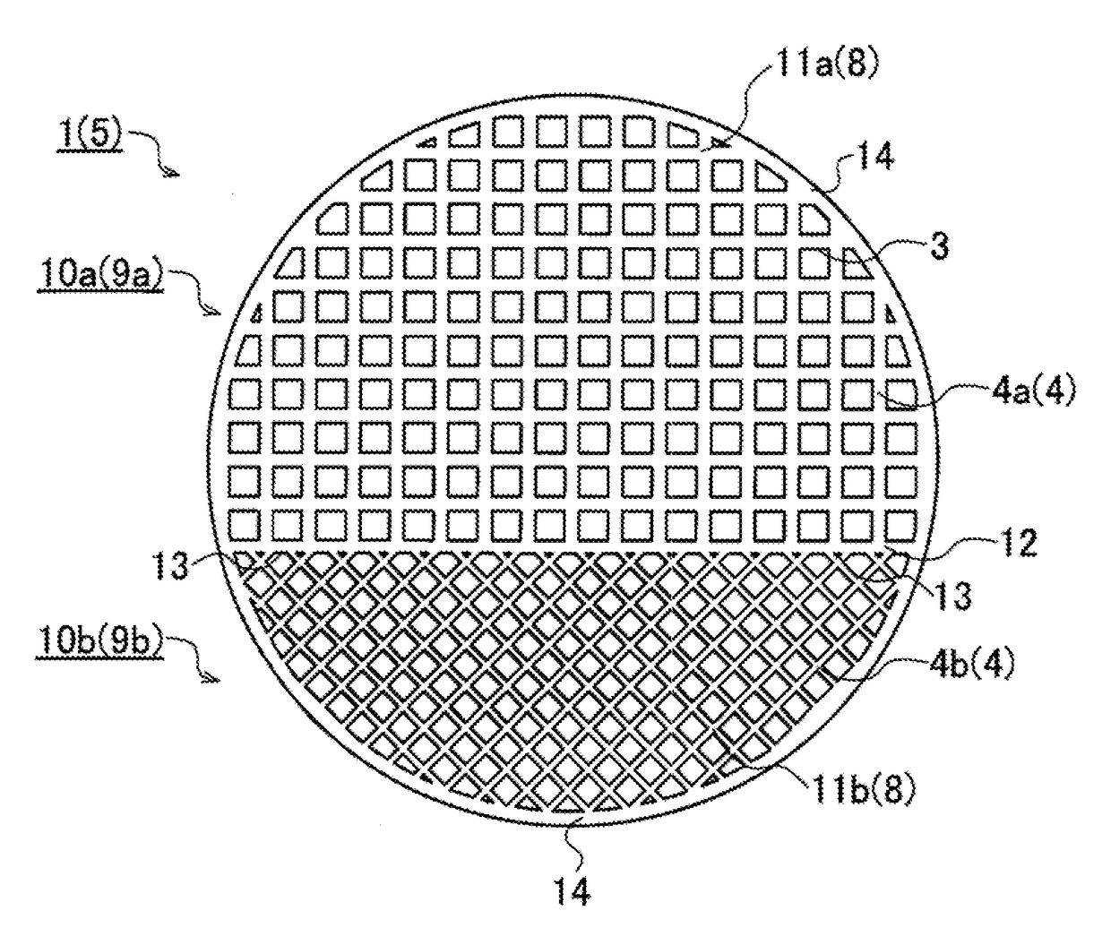
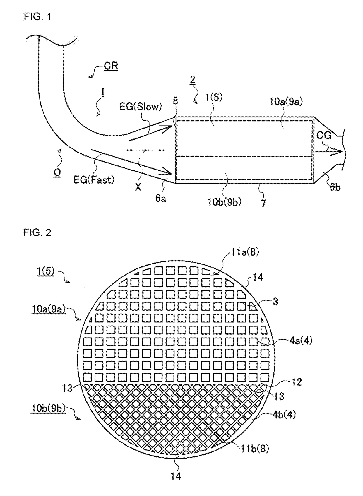
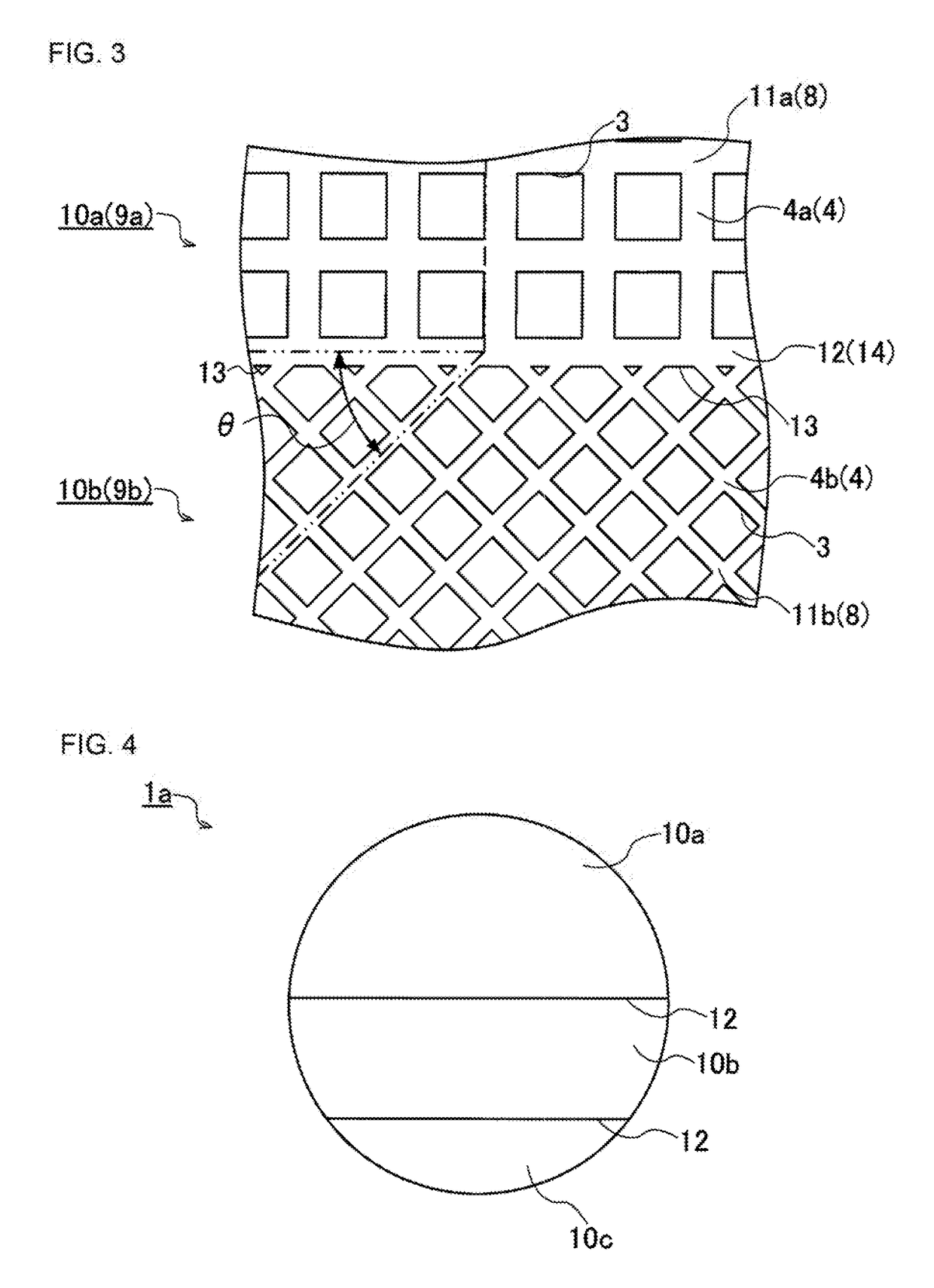
The present invention provides a honeycomb structure that can achieve uniformity of flow rate and treatment of a fluid, without being limited by the installation place of an exhaust gas purifying device or the shape of the exhaust channel route. The structure has multiple cell regions with different cell structures to correct non-uniformity of flow rate and eliminate uneven treatment. The structure also has partition walls that are tilted to decrease pressure loss and inhibit cracks. The manufacturing method of the honeycomb structure can monolithically form it or combine separate cell regions. The technical effects are high NOx purification efficiency, decreased pressure loss, and inhibition of crack generation.

Problems solved by technology

However, a honeycomb structure for use in the above exhaust gas purifying device has the possibility of causing disadvantages mentioned below.
When the exhaust gas purifying device 100 described above is mounted in a diesel car or the like, its installation place is often limited.

Method used


Image

  • Honeycomb structure, and manufacturing method of honeycomb structure
  • Honeycomb structure, and manufacturing method of honeycomb structure
  • Honeycomb structure, and manufacturing method of honeycomb structure

Examples


examples

(1) Honeycomb Structure (Examples 1 to 20 and Comparative Examples 1 to 4)

[0072]On the basis of the above-mentioned manufacturing method of the honeycomb structure, a plurality of honeycomb structures (Examples 1 to 20 and Comparative Examples 1 to 4) were prepared each of which was constituted of a plurality of cell regions having different cell structures. Table 1 shows a summary of the results of Examples 1 to 20 and Comparative Examples 1 to 4 as follows. Table 1 shows “X / Y” in each of columns of a first cell structure, a second cell structure and a third cell structure, in which X is a length per 1 / 1000 inches and Y is a cell number per square inch.

TABLE 1Ratiooccupiedby first cellFirst cell regionSecond cell regionThird cell regionregion FirstSecondThirdPartition Cell Partition Cell Partition Cell to area Ratio ofcellcellcellwalldensity / walldensity / walldensity / of wholein-Tilt struc-struc-struc-thickness / cells / thickness / cells / thickness / cells / structure completeangleturetureturem...


PUM

PropertyMeasurementUnit
Fractionaaaaaaaaaa
Fractionaaaaaaaaaa
Angleaaaaaaaaaa

Abstract

A honeycomb structure has partition walls defining a plurality of polygonal cells which become through channels for a fluid, a structure end face vertical to an axial direction has at least two cell regions possessing mutually different cell structures and surrounded by circumferential portions, and in the cell regions adjacent to each other, to first partition walls of a first cell structure of one first cell region, second partition walls of a second cell structure of the other or second cell region are tilted.

Description

[0001]“The present application is an application based on JP-2016-063507 filed on Mar. 28, 2016 with Japan Patent Office, the entire contents of which are incorporated herein by reference.”BACKGROUND OF THE INVENTION[0002]1. Field of the Invention[0003]The present invention relates to a honeycomb structure, and a manufacturing method of the honeycomb structure, and more particularly, it relates to a honeycomb structure which is capable of achieving uniformity of a flow rate of a fluid such as an exhaust gas to pass through the honeycomb structure, and a manufacturing method of the honeycomb structure.[0004]2. Description of the Related Art[0005]Heretofore, an exhaust gas emitted from an internal combustion engine such as a car engine includes toxic substances such as carbon monoxide (CO), hydrocarbons (HC) and nitrogen oxides (NOx). Natural environments, human bodies and others are adversely affected, and hence the toxic substances cannot be discharged to the air as they are. To eli...

Claims


Application Information

Patent Timeline
IPC IPC(8): F01N3/28B01J37/00B28B11/24B01J35/04B28B3/26B01D53/94
CPCF01N3/2828B28B3/269B01D53/9431B28B11/243B01J35/04F01N2570/14B01D2255/9202B01D2255/9032B01D2255/9035B28B2003/203B01J37/0009C04B38/00F01N3/2803C04B38/0006C04B38/0009C04B2111/00793C04B2111/0081B01D2251/2062B01D53/9472F01N2330/60F01N2330/06B01D2258/012B01J35/56C04B35/00
Inventor HIROSE, SHOGONAKAO, SHIORI
Owner NGK INSULATORS LTD
Learn More