
Method for producing organic microdisk structure

Active Publication Date: 2017-09-14
KYUSHU UNIV +1
View PDF1 Cites 7 Cited by
  • Summary
  • Abstract
  • Description
  • Claims
  • Application Information

AI Technical Summary

Benefits of technology

The invention is a new way to make small organic structures using an inkjet printing process. This method uses a special polymer and a laser dye, which makes it possible to create a laser that can be easily ignited. The process is carried out at room temperature and pressure, which makes it more versatile than other methods that require high vacuum, heat, and stimulation. The new method can be used for creating biosensing devices and other practical applications.

Problems solved by technology

Up until now, organic microdisk fabrication has been carried out using primarily photolithography (see Non-Patent Documents 1 to 3), but the complexity of such processes has been a drawback.
However, because inkjet printing generally can discharge only low-viscosity inks having viscosities ranging from several mPa·s to several tens of mPa·s, achieving a high polymer concentration within the ink is a challenge.
Hence, one drawback is that only thin films having thicknesses of up to about several hundred nm can be created.

Method used


Image

  • Method for producing organic microdisk structure
  • Method for producing organic microdisk structure
  • Method for producing organic microdisk structure

Examples


production example 1

Preparation of First Ink

[0161]Using a procedure similar to that in Working Example 1 of WO 2010 / 137724, a fluorinated acrylic-based HBP synthesized from ethylene glycol dimethacrylate, 1H,1H,5H-octafluoropentyl methacrylate and methyl 2,2′-azobisisobutyrate was dissolved in 1,4-dioxane, thereby preparing a first ink having a concentration of 10 wt %.

production example 2

Preparation of Second Ink

[0162]Using a procedure similar to that in Working Example 98 of WO 2010 / 128661, a triazine-type HBP synthesized from m-phenylenediamine, 2,4,6-trichloro-1,3,5-triazine and aniline, and the laser dye LDS798 (Exiton) were both dissolved in cyclohexanone, thereby preparing a second ink having a polymer concentration of 10 wt % and containing 2 mM of dye.

working example 1

Fabrication of Microdisk Structure

(1) Cladding Layer-Forming Step

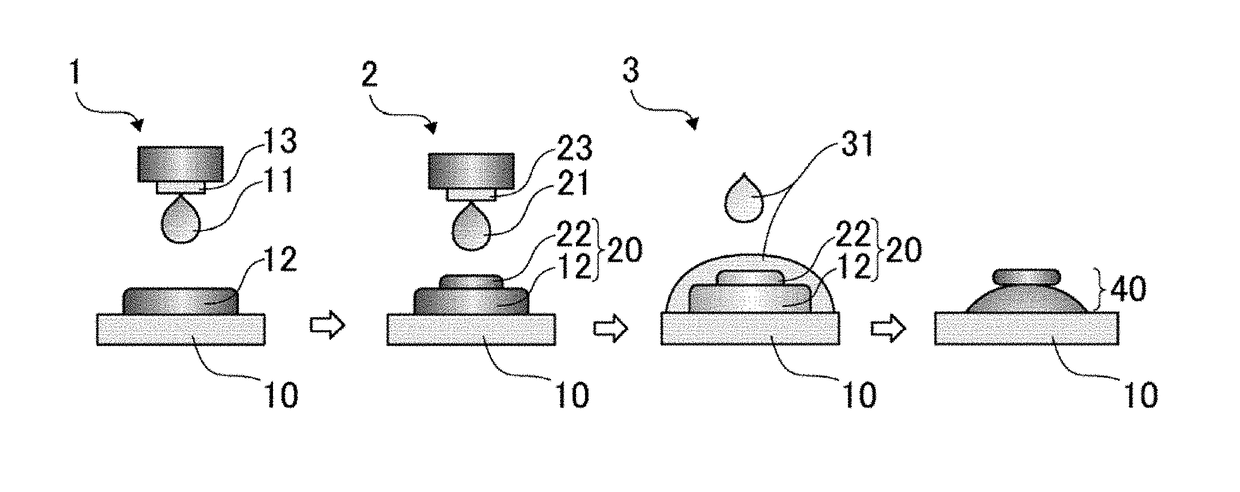
[0163]As shown in FIG. 1, using a 70 μm diameter inkjet nozzle 13, printing was carried out by discharging and building up five shots of the first ink 11 obtained in Production Example 1 onto a PET substrate 10 so as to form a cladding layer 12 having a spot diameter of 250 to 300 μm.

(2) Core Layer-Forming Step

[0164]Next, using a 50 μm diameter inkjet nozzle 23, the second ink 21 prepared in Production Example 2 was discharged and printed as a single shot onto the center of the cladding layer 12 formed above, thereby forming a core layer 22 having a spot diameter of about 100 μm and producing a stack 20 of the cladding layer 12 and the core layer 22.

(3) Etching Step

[0165]Using 1,4-dioxane as the etchant 31, the operation of carrying out a 1-second etch by charging 0.2 μL of etchant 31 per individual stack 20 in a single etching pass and then removing the etchant 31 by soaking it up with clean paper lateral to the stack...


PUM

PropertyMeasurementUnit
Concentrationaaaaaaaaaa
Structureaaaaaaaaaa
Refractive indexaaaaaaaaaa

Abstract

A method for producing an organic microdisk structure 40, which is characterized by comprising: a cladding layer formation step 1 wherein a cladding layer 12 is formed by printing a first ink 11 that contains a fluorine-containing hyperbranched polymer on a substrate 10 by an inkjet method; a core layer formation step 2 wherein a core layer 22 is formed by printing a second ink 21 that contains a laser dye and a triazine-based hyperbranched polymer containing no fluorine on the cladding layer 12 by an inkjet method; and an etching step 3 wherein the cladding layer 12 is etched using a solvent 31 that dissolves only the fluorine-containing hyperbranched polymer. Consequently, an unconventional novel method for producing an organic microdisk structure with use of an inkjet method is able to be provided.

Description

TECHNICAL FIELD[0001]This invention relates to a method of fabricating an organic microdisk structure. More specifically, the invention relates to a method of fabricating an organic microdisk structure using the inkjet printing process.BACKGROUND ART[0002]Microdisk structures and other microcavities are able to confine light at a high efficiency by repeated total reflection of the light at interfaces, making it possible to achieve high interactions between matter and light. Potential applications include microlasers capable of lasing at ultralow thresholds, optical signal processing, integrated optics, and high-sensitivity sensors such as biosensors.[0003]As microdisk-forming materials, organic substances provide a number of advantages over inorganic substances. For example, organic substances can be doped with various dyes, in addition to which they are inexpensive and amenable to fabrication.[0004]Up until now, organic microdisk fabrication has been carried out using primarily pho...

Claims


Application Information

Patent Timeline
IPC IPC(8): H01S3/06C09D11/107C23C22/82C09D11/328C09D11/03B41J2/01H01S3/213C09D11/102
CPCH01S3/0627H01S3/213C09D11/107C23C22/82C09D11/328C09D11/03B41J2/01C09D11/102C09D11/38G02B6/12007G02B6/132G02B6/29341H01S3/168
Inventor OKI, YUJIYOSHIOKA, HIROAKIYASUI, KEIOZAWA, MASAAKI
Owner KYUSHU UNIV
Learn More