Vehicular damper device

Inactive Publication Date: 2013-09-19
TOYOTA JIDOSHA KK
View PDF6 Cites 10 Cited by
  • Summary
  • Abstract
  • Description
  • Claims
  • Application Information

AI Technical Summary

Benefits of technology

The present invention provides a vehicular damper device that includes a dynamic damper and an elastic member operatively connecting the dynamic damper to the engine. By connecting the dynamic damper to the structural body having the larger inertia mass, the device achieves a high damping effect during generation of torsional resonance. The device does not increase vibration transmission sensitivity at other frequencies. In a preferred form of the invention, a friction mechanism consisting of friction plates and a coned-disk spring is disposed between the first inertial body and the second inertial body, further enhancing the vibration damping effect by adjusting the friction coefficients and rigidity of the coned-disk spring.

Problems solved by technology

Keeping pace with a recent tendency toward the use of a lean-burn engine for improving the fuel economy, which leads to instability of combustion of the engine, resonance generating forces based on lower-order components such as revolution 1-order and revolution 0.5-order components which do not conventionally pose a problem also tend to increase.
Although a torsional resonance frequency band of a revolution 2-order drive system is set to be not higher than normal operating speeds of the engine, torsional resonance of a revolution lower-order drive system is generated at the normal operating speeds of the engine, giving rise to a problem of an influence on NV characteristics and drivability of the vehicle.
In the dual-mass flywheel 1 disclosed in Patent Document 1, however, the dynamic damper 2 is disposed in the secondary flywheel 12, so that a vibration energy absorbed by the dynamic damper 2 is small, whereby the torsional vibration is difficult to be effectively damped.
Accordingly, the dual-mass flywheel 1 disclosed in Patent Document 1 is not capable of achieving a high damping effect with respect to not only the torsional resonance of the above-indicated revolution 2-order drive system, but also the torsional resonance of low-order drive systems such as revolution 1-order and revolution 0.5-order drive systems.
However, these methods cause an increase of vibration transmission sensitivity at a frequency higher than the natural frequency, and generation of booming, rattling and other noises of the engine.

Method used


Image

  • Vehicular damper device
  • Vehicular damper device
  • Vehicular damper device

Examples


embodiment

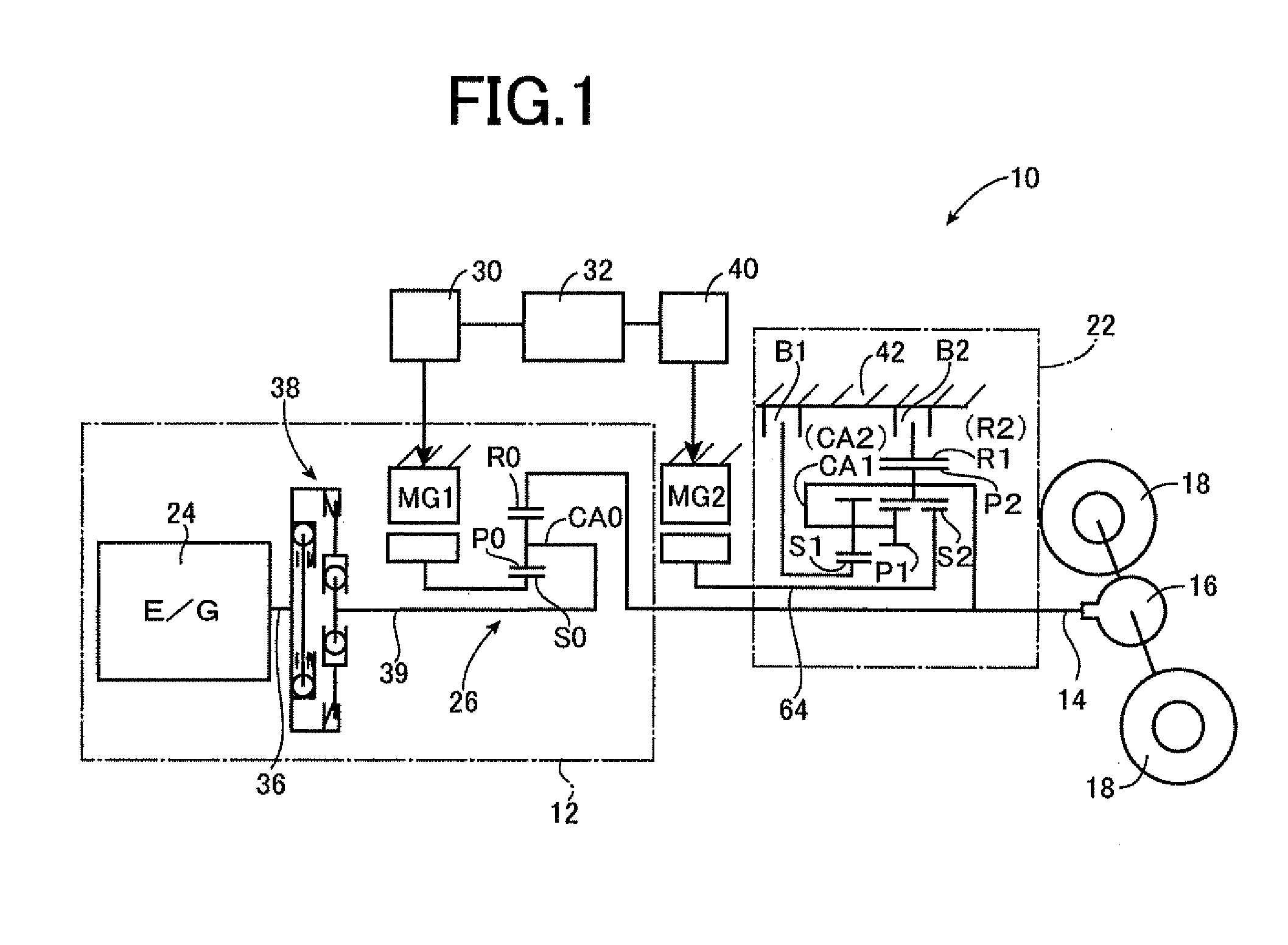
[0017]FIG. 1 is the schematic view showing the arrangement of a vehicular drive system 10 of a hybrid type to which the present invention is suitably applicable. As shown in FIG. 1, the vehicular drive system 10 is configured such that a torque of a primary drive power source in the form of a first drive power source 12 is transmitted to a wheel drive output shaft 14 functioning as an output member of a vehicle, and is then transmitted from the wheel drive output shaft 14 to a pair of right and left drive wheels 18 through a differential gear device 16. The present vehicular drive system 10 is provided with a second drive power source in the form of a second electric motor MG2 which is operable selectively in a vehicle driving mode for generating a vehicle drive force or a regenerative operation mode for regenerating an electric energy. This second electric motor MG2 is connected to the above-described wheel drive output shaft through an automatic transmission 22. Accordingly, the o...


PUM


Abstract

A vehicular damper device interposed between an engine and an output shaft and provided with a dual-mass flywheel includes: a first inertial body in the form of a disk connected to a crankshaft of said engine and rotatable about an axis of said crankshaft; a torsional damping portion interposed between said first inertial body and said output shaft; a second inertial body in the form of a disk rotatable about said axis and having a smaller outside diameter than said first inertial body, said second inertial body cooperating with said first inertial body to constitute said dual-mass flywheel; and an elastic member interposed between said first inertial body and said second inertial body and operatively connecting said first and second inertial bodies such that said elastic member is elastically deformable according to an amount of relative rotation of the first and second inertial bodies.

Description

TECHNICAL FIELD[0001]The present invention relates to a vehicular damper device, and more particularly to a construction of a damper capable of achieving a high damping effect.BACKGROUND ART[0002]There is well known a vehicular damper device which is provided in a power transmitting path between an engine and an output shaft, and which is constructed to restrict transmission of a torsional vibration during power transmission. Patent Document 1 discloses an example of such a vehicular damper device in the form of a dual-mass flywheel. In the dual-mass flywheel 1 disclosed in Patent Document 1, primary flywheel 11 and a secondary flywheel 12 are connected to each other through a torsion spring 13, and the secondary flywheel 12 is provided with a dynamic damper 2 which consists of a mass member 21 and an elastic body 22.[0003]In the damper device constructed as described above, an inertia mass of the mass member 21 and rigidity of the elastic body 22 are adjusted such that a natural fr...

Claims


Application Information

Patent Timeline
IPC IPC(8): F16F15/14F16F15/31F16D3/12
CPCF16F15/134F16D3/12F16F15/30F16F15/31F16F15/1485
Inventor SAKAI, KAZUNORISUGIYAMA, MASATAKAMORITA, YOSHINORITAKEMURA, TADASHI
Owner TOYOTA JIDOSHA KK
Why Eureka
Try Eureka