Surface structure forming method for zirconia-based ceramics, and zirconia-based ceramics
- Summary
- Abstract
- Description
- Claims
- Application Information
AI Technical Summary
Benefits of technology
Problems solved by technology
Method used
Image
Examples
first embodiment
[0080]The present embodiment is described below with reference to FIGS. 4 and 5. FIG. 4 is a schematic diagram showing a laser surface-processing device used in the present embodiment. The device shown in FIG. 4 includes a laser source 1, a power control unit 2, a polarization control unit 3, a beam shaping unit 4, a condensing lens 5, and an irradiation stage 6. The power control unit 2 controls the power of a laser beam (unit: W), or the energy per pulse of a laser beam (unit: J). The polarization control unit 3 controls the direction of polarization of a laser beam and the state of the polarization, more specifically, linearly polarized light, elliptically polarized light, or circularly polarized light. The beam shaping unit 4 controls the beam shape, the intensity distribution inside of a beam, and the beam propagation direction. The irradiation stage 6 is a stage where a workpiece is mounted, and that is freely movable between positions (x, y, z, θ, φ) relative to a laser beam....
second embodiment
[0087]A laser source different from that used in First Embodiment was used in the present embodiment. Irradiating a linearly polarized laser beam (Yb-doped KGW (KGd(WO4)2; a wavelength of 1.03 microns, a pulse width of 200 fs) on a zirconia-based ceramic surface formed a periodic microstructured irregularities of a parallel stripe pattern on the surface. The laser beam was irradiated 50 shots. The direction of polarization of the linearly polarized laser beam was parallel to the stripes. The periodic structure had a period of about 1.05 μm / cycle, on average. The period observed had about the same or a slightly longer than the wavelength of the irradiated laser beam. The surface structure was similar to that obtained in First Embodiment, despite the different laser source.
third embodiment
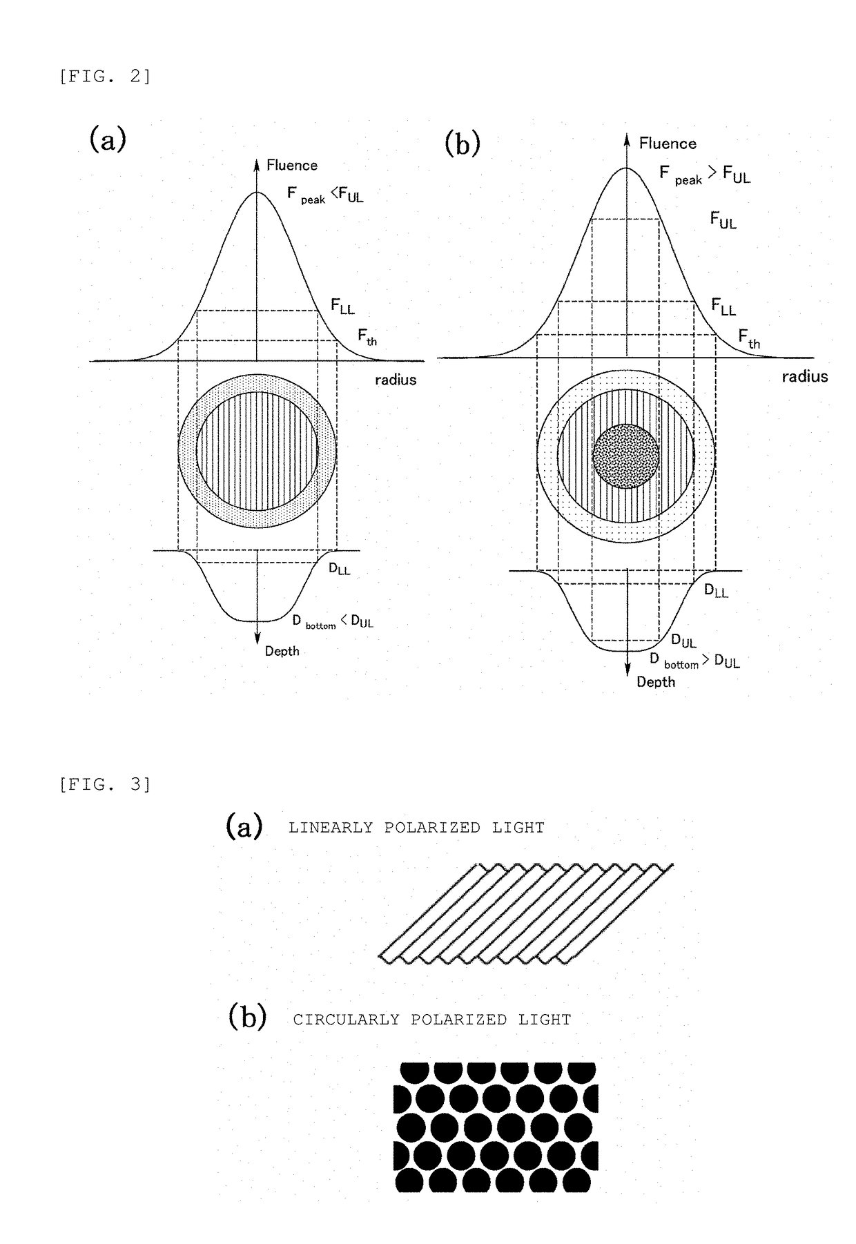
[0088]The present embodiment is described with reference to FIGS. 6, 7, and 8. The present embodiment describes the optimum conditions for forming the periodic structure, among others.
[0089]The etch rate refers to the depth D of an etched hole per shot of a laser beam. In the embodiment, depth D is the mean value determined by, for example, dividing the depth of a hole by the number of shots, 40, irradiated to form the hole. The unit is nm / shot. Here, the shot in the denominator means that the depth is the average value per unit shot.
[0090]FIG. 6 is a diagram representing the relationship between etch rate and a surface state, for example, the presence or absence of a stripe-pattern surface periodic structure, after 40 shots of a linearly polarized laser beam (TiS; a wavelength of 810 nm, 80 fs). In the figure, the horizontal axis represents the etch rate (unit: nm / shot), and the vertical axis represents the state of a laser spot mark in four levels: “No mark”, “No periodic structur...
PUM
| Property | Measurement | Unit |
|---|---|---|
| Time | aaaaa | aaaaa |
| Time | aaaaa | aaaaa |
| Structure | aaaaa | aaaaa |
Abstract
Description
Claims
Application Information
 - R&D
- Intellectual Property
- Life Sciences
- Materials
- Tech Scout
- Unparalleled Data Quality
- Higher Quality Content
- 60% Fewer Hallucinations
Browse by: Latest US Patents, China's latest patents, Technical Efficacy Thesaurus, Application Domain, Technology Topic, Popular Technical Reports.
© 2025 PatSnap. All rights reserved.Legal|Privacy policy|Modern Slavery Act Transparency Statement|Sitemap|About US| Contact US: help@patsnap.com


