Light reflecting film, production method for light reflecting film, decorative molding method for light reflecting film, laminated glass, and curved surface body

a production method and technology of light reflecting film, applied in the direction of optical filters, layered product treatment, synthetic resin layered products, etc., can solve the problems of residual stress, reduced optical reflectance, and inferior so as to improve the self-restoring property of stretched sections, improve the effect of deterioration and excellent scratch resistan

Inactive Publication Date: 2017-09-07
KONICA MINOLTA INC
View PDF3 Cites 11 Cited by
  • Summary
  • Abstract
  • Description
  • Claims
  • Application Information

AI Technical Summary

Benefits of technology

[0026]According to the above-described means of the present invention, it is possible to provide a light reflecting film which allows an improvement of a deterioration of self-restoring property of a stretched section when the film is stretched and attached to a curved surface and has excellent scratch resistance and light resistance, a method for producing the light reflecting film, a method for decorative molding of the light reflecting film, laminated glass, and a curved surface body.
[0027]Although the mechanism for exhibiting the effect or the working mechanism of the present invention remains unclear, it is believed as follows.
[0028]A polymer having self-restoring property can restore elastic deformation against external stress and also can self-restore small scratches on a surface. Thus, by forming a self-restoring layer containing this polymer as a surface protecting layer, it is expected to have an excellent effect of impact resistance and scratch resistance. Meanwhile, once the self-restoring layer undergoes plastic deformation, deformations like scratch cannot be restored.
[0029]When a light reflecting film is attached to a curved surface body like a window of an automobile, the light reflecting film is stretched in a curved surface part. According to the constitution of Patent Literature 1 described above, the self-restoring layer is stretched with a substrate film so that the attachment to various curved surface shapes can be made. However, according to that constitution, there is a problem of having an easy occurrence of scratches in a stretched section as the scratch resistance (self-restoring property) of a stretched section is inferior to the scratch resistance of a non-stretched section.
[0030]In this regard, it is believed that, as a strong deformation stress is applied from a substrate side to a self-restoring layer at the time of attachment to a curved surface shape, part of the self-restoring layer on the substrate side in a stretched section is plasticized so that an elastic deformation region in layer thickness direction is reduced, yielding deteriorated self-restoring performance.
[0031]The present invention is characterized in that the elasticity of a self-restoring layer is controlled to a specific range and a buffer layer is formed between a light reflecting body and the self-restoring layer. It was found that, according to such constitution, the deformation stress at substrate side which occurs as a result of stretching for attachment to a curved surface shape is absorbed by the self-restoring layer and buffer layer, and thus the substrate side of the self-restoring layer is not plasticized and the self-restoring performance of a stretched section is not deteriorated.

Problems solved by technology

However, simple incorporation of a ultraviolet (UV) absorbing agent or a light stabilizer (in the present application, also referred to as HALS) to a common hard coat material is not enough to deal with long-term irradiation with sunlight in an outdoor environment, and a problem occurs in that, as the substrate deteriorates, optical reflectance is lowered.
As such, a problem occurs in that, when attachment is carried out with a common hard coat material, scratches on a hard coat layer are yielded due to residual stress after the attachment.
As such, there is a problem that the self-restoring property of a stretched section becomes inferior to the self-restoring property of a non-stretched section and the stretched section has insufficient scratch resistance.

Method used


Image

  • Light reflecting film, production method for light reflecting film, decorative molding method for light reflecting film, laminated glass, and curved surface body
  • Light reflecting film, production method for light reflecting film, decorative molding method for light reflecting film, laminated glass, and curved surface body
  • Light reflecting film, production method for light reflecting film, decorative molding method for light reflecting film, laminated glass, and curved surface body

Examples


synthetic example 1

[0087]To a 4-necked flask equipped with a stirrer, a thermometer, and a condenser, 415.8 parts by mass of toluene, 100 parts by mass of 1,2,4-butane tricarboxylic acid (acid number: 886), 315.8 parts by mass of 4-hydroxybutylacrylate monoglycidyl ether [Nippon Kasei Chemical Co., Ltd., 4-HBAGE], and 0.1 part by mass of hydroquinone monomethyl ether were added and heated to 100° C. After confirming complete dissolution of 1,2,4-tricarboxylic acid, 2 parts by mass of TPP (triphenylphosphine) were added. After maintaining it at the same temperature for 24 hours, the reaction was terminated. As a result, epoxy acrylate having solid content of 50% by mass and acid number of 4.2 mgKOH / g (in terms of solid content) was obtained. Yield was 96.1%.

[0088]Examples of the active energy ray curable resin with an alkyl chain skeleton or an alkylene oxide skeleton include urethane (meth)acrylate, which is obtained by reacting (meth)acrylate ((P1) shown below) that is obtained by adding 1 to 20 mole...

example 1

>

[Light Reflecting Body 1: Production of the IR Reflecting Film 1]

[0384]As a transparent substrate film, a polyethylene terephthalate film with thickness of 50 μm (Cosmo Shine A4300, manufactured by TOYOBO CO., LTD., both surfaces with easy-adhesion treatment, abbreviation: PET) was used.

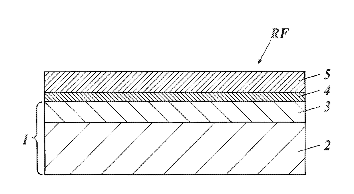
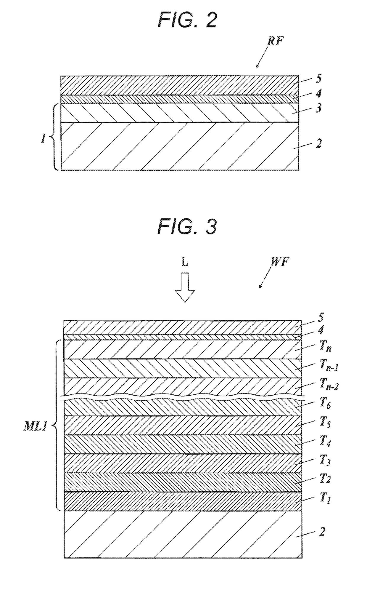
[0385]Subsequently, as a light reflecting layer, the IR reflecting film 1 in which a high refractive index layer containing the first water soluble binder resin and the first metal oxide particle and a low refractive index layer containing the second water soluble binder resin and the second metal oxide particle are alternately laminated was produced as shown below (corresponding to FIG. 3).

[0386](1) Forming of Undercoating Layer

[0387]A coating solution for an undercoating layer was applied on a transparent substrate film so as to have coating of 15 ml / m2 using an extrusion coater. Then, after passing through a windless zone (1 second) at 50° C., it was dried for 30 seconds at 120° C. to obtain a su...

example 2

>

[Light Reflecting Body 3: Production of Film Mirror]

[0468]As a transparent substrate film, a biaxially stretched polyester film (polyethylene terephthalate film, thickness of 25 μm) was used. On a single surface of the polyethylene terephthalate film, a resin in which a polyester resin (poly ester(ester) SP-181 manufactured by The Nippon Synthetic Chemical Industry Co., Ltd.), a melamine resin (SUPER BECKAMINE J-820 manufactured by DIC Corporation), TDI based isocyanate (2,4-tolylene diisocyanate), and HDMI (registered trademark) based isocyanate (1,6-hexamethylene diisocyanate) are mixed in toluene in resin solid content ratio of 20:1:1:2 to have solid matter concentration of 10% by mass was applied by gravure coating method to form an anchor layer with thickness of 0.1 μm. On top of the anchor layer, a silver reflecting layer with thickness of 100 nm was formed as a silver reflecting layer by vacuum vapor deposition method. On top of the silver reflecting layer, a resin in which ...


PUM

PropertyMeasurementUnit
light reflectanceaaaaaaaaaa
light wavelengthaaaaaaaaaa

Abstract

A light reflecting film may be provided that improves the self-restoring property of a stretched section thereof when stretched and attached to a curved surface and that has excellent scratch resistance and light resistance, a production method for the light reflecting film, a decorative molding method may also be provided for the light reflecting film, laminated glass, and a curved surface body.

Description

CROSS REFERENCE TO RELATED APPLICATIONS[0001]This is the U.S. national stage of application No. PCT / JP2015 / 072742, filed on Aug. 11, 2015. Priority under 35 U.S.C. §119(a) and 35 U.S.C. §365(b) is claimed from Japanese Application No. 2014-168931, filed Aug. 22, 2014, the disclosure of which is also incorporated herein by reference.TECHNICAL FIELD[0002]The present invention relates to a light reflecting film, a method for producing a light reflecting film, a method for decorative molding of a light reflecting film, laminated glass, and a curved surface body. More specifically, the present invention relates to a light reflecting film which allows an improvement of a deterioration of self-restoring property of a stretched section when the film is stretched and attached to a curved surface and has excellent scratch resistance and light resistance, a method for producing the light reflecting film, a method for decorative molding of the light reflecting film, laminated glass, and a curve...

Claims


Application Information

Patent Timeline
Patent Type & Authority Applications(United States)
IPC IPC(8): G02B5/20G02B5/26B32B37/06B29C65/48B32B7/02B32B7/12
CPCG02B5/208B32B7/02B32B7/12B29L2011/00B29C65/48G02B5/26B32B2307/416B32B37/06B32B17/10036B32B17/1011B32B17/10201B32B17/10761B32B27/08B32B37/02G02B5/0816G02B5/0841G02B5/085B32B2309/02B32B2315/08B32B7/04B32B7/06B32B9/02B32B9/045B32B23/04B32B23/08B32B27/06B32B27/20B32B27/28B32B27/285B32B27/288B32B27/30B32B27/302B32B27/306B32B27/308B32B27/32B32B27/36B32B27/365B32B27/40B32B2250/04B32B2255/10B32B2255/205B32B2255/26B32B2255/28B32B2264/0214B32B2264/10B32B2264/102B32B2264/104B32B2270/00B32B2307/21B32B2307/302B32B2307/306B32B2307/31B32B2307/402B32B2307/412B32B2307/50B32B2307/51B32B2307/518B32B2307/536B32B2307/554B32B2307/558B32B2307/584B32B2307/71B32B2307/712B32B2307/7242B32B2307/732B32B2307/736B32B2307/748B32B2307/752B32B2419/00B32B2457/00B32B2457/208B32B2509/00B32B2605/006B32B2605/08B32B2605/10B32B2605/12B32B2605/18
Inventor MORITA, TAKAAKI
Owner KONICA MINOLTA INC
Why Eureka
Try Eureka