Shield wire

a shield wire and shield technology, applied in the field of shield wire, can solve the problems of poor bending resistance of conductive foil, burdensome removal work, poor electromagnetic shield property, etc., and achieve the effect of facilitating terminal processing, excellent bending resistance and electromagnetic shield property

Active Publication Date: 2017-08-10
TATSUTA ELECTRICWIRE & CABLE
View PDF16 Cites 5 Cited by
  • Summary
  • Abstract
  • Description
  • Claims
  • Application Information

AI Technical Summary

Benefits of technology

[0030]The present invention has the above-mentioned configuration to ensure providing the shield wire that is excellent in the bending resistance and the electromagnetic shield property and can facilitate the terminal processing.

Problems solved by technology

Additionally, the braided body is braided so that the work of removing becomes burdensome.
Therefore, compared with using the braided body, using conductive foil may have poor bending resistance and poor electromagnetic shield property.

Method used


Image

  • Shield wire
  • Shield wire

Examples


Embodiment Construction

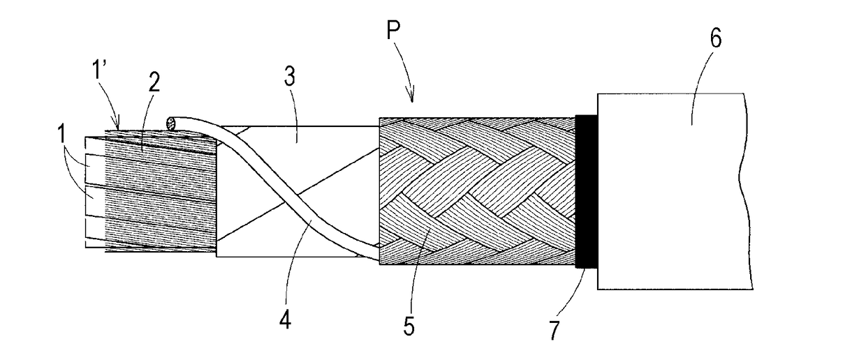
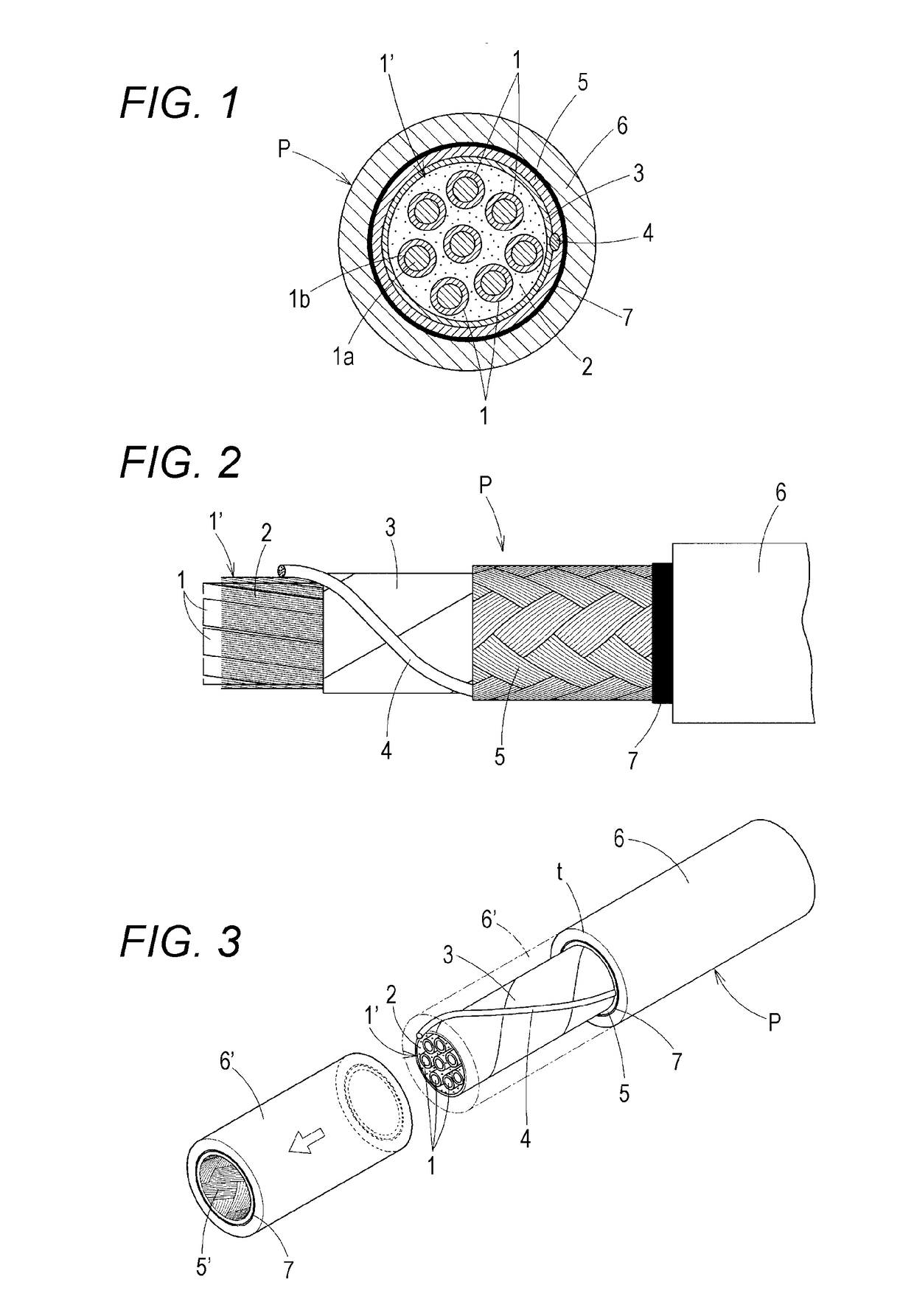
[0034]FIG. 1 and FIG. 2 illustrate one embodiment of a shield wire P according to the present invention. This shield wire P is for a robot cable. The shield wire P is formed of eight twisted insulated core wires 1, an inclusion 2 between these respective insulated core wires 1, a tape 3 laterally wound around an outer periphery of a core 1′ formed of these insulated core wires 1 and inclusion 2, a drain wire 4, which is over a whole wire length, disposed on an outer surface of the tape 3, a conductive fiber braided body 5 formed on an outer peripheral surface of the press tape 3 so as to interpose the drain wire 4, a sheath (a protecting layer) 6 that forms an outer peripheral surface of the braided body 5, and an adhesive layer 7 between the braided body 5 and sheath 6.

[0035]The insulated core wire 1 has an insulating coating 1b, which is polyvinyl chloride or the like, disposed on a copper alloy twisted wire 1a whose cross-sectional area is 0.2 mm2. The number, an outside diameter...


PUM

PropertyMeasurementUnit
cross-sectional areaaaaaaaaaaa
conductiveaaaaaaaaaa
circular shapeaaaaaaaaaa

Abstract

A shield wire is formed of eight twisted insulated core wires 1, an inclusion 2 between these respective insulated core wires 1, a tape 3 laterally wound around an outer periphery of a core formed of the insulated core wires and inclusion, a drain wire 4 disposed on an outer surface of the tape, a conductive fiber braided body 5 formed on an outer peripheral surface of the tape so as to interpose the drain wire, a sheath 6 that forms an outer peripheral surface of the braided body, and an adhesive layer 7 between the braided body and sheath. A braided body 5′ is adhesively integrated to the sheath 6′ by an adhesive layer; thus, the braided body 5′ is stripped with the sheath. This eliminates a need for a removal work of the braided body after stripping the sheath, thus ensuring good workability of the terminal processing.

Description

TECHNICAL FIELD[0001]The present invention relates to a shield wire having a shield layer (a shielding layer) against electromagnetic wave.RELATED ART[0002]This type of shield wire includes a shield wire having a configuration where a plurality of insulated core wires is twisted to form a core, and then, a conductive fiber braided body is formed on an outer periphery of this core, and furthermore, a sheath (an external cover) is disposed outside the conductive fiber braided body (PATENT LITERATURES 1 and 2). The braided body is braided with copper-plating polyester fiber (PATENT LITERATURE 1) or carbon fiber (PATENT LITERATURE 2). The sheath is disposed by extrusion molding of resin such as vinyl chloride (PATENT LITERATURE 1).[0003]This type of shield wire also includes a shielded twisted pair cable where a conductive foil such as an aluminum foil covering an outer periphery of a core formed by twisting insulated core wires, and an external insulator (a sheath) are adhered by an ad...

Claims


Application Information

Patent Timeline
Patent Type & Authority Applications(United States)
IPC IPC(8): H05K9/00H01B7/18H01B7/02
CPCH05K9/0098H01B7/18H01B7/0216H01B7/188H01B11/1091
Inventor URASHITA, KIYOTAKAKAWAKAMI, YOSHINORI
Owner TATSUTA ELECTRICWIRE & CABLE
Why Eureka
Try Eureka