
Battery

a battery and battery technology, applied in the field of batteries, can solve the problems of high temperature of these parts, impaired adhesion between these parts and the external metallic member, and increased likelihood of situations, and achieve the effect of reducing the temperature and melting point, and restrainting the situation

Inactive Publication Date: 2017-08-10
TOYOTA JIDOSHA KK
View PDF3 Cites 9 Cited by
  • Summary
  • Abstract
  • Description
  • Claims
  • Application Information

AI Technical Summary

Benefits of technology

The patent describes a battery design that prevents heat from affecting the external resin part when a rivet is formed to attach a metallic member to the battery case. This design also includes a heat transfer inhibiting portion that prevents heat transfer from the metallic member to the resin part, which can help prevent deformation or deterioration of the resin. This design is cost-effective and can improve the battery's performance.

Problems solved by technology

However, when spot-like weld beads are formed by irradiation with pulse-like energy beams such as laser beams and electron beams, parts of the external resin member immediately below the weld beads receive heat intensively from these weld beads through external metallic member, and temperature of these parts can be high.
Then, in these parts, resin that forms the external resin member can be deteriorated due to the heat, which could cause a situation where adhesion between these parts and the external metallic member and / or adhesion between these parts and the battery case are impaired.
Then, it is more likely that heat is transferred from the weld bead to the axially inner side of the weld bead, and a situation is thus more likely to occur where adhesion is deteriorated at a part of the external resin member on the axially inner side of the weld bead.

Method used


Image

  • Battery
  • Battery
  • Battery

Examples


Embodiment Construction

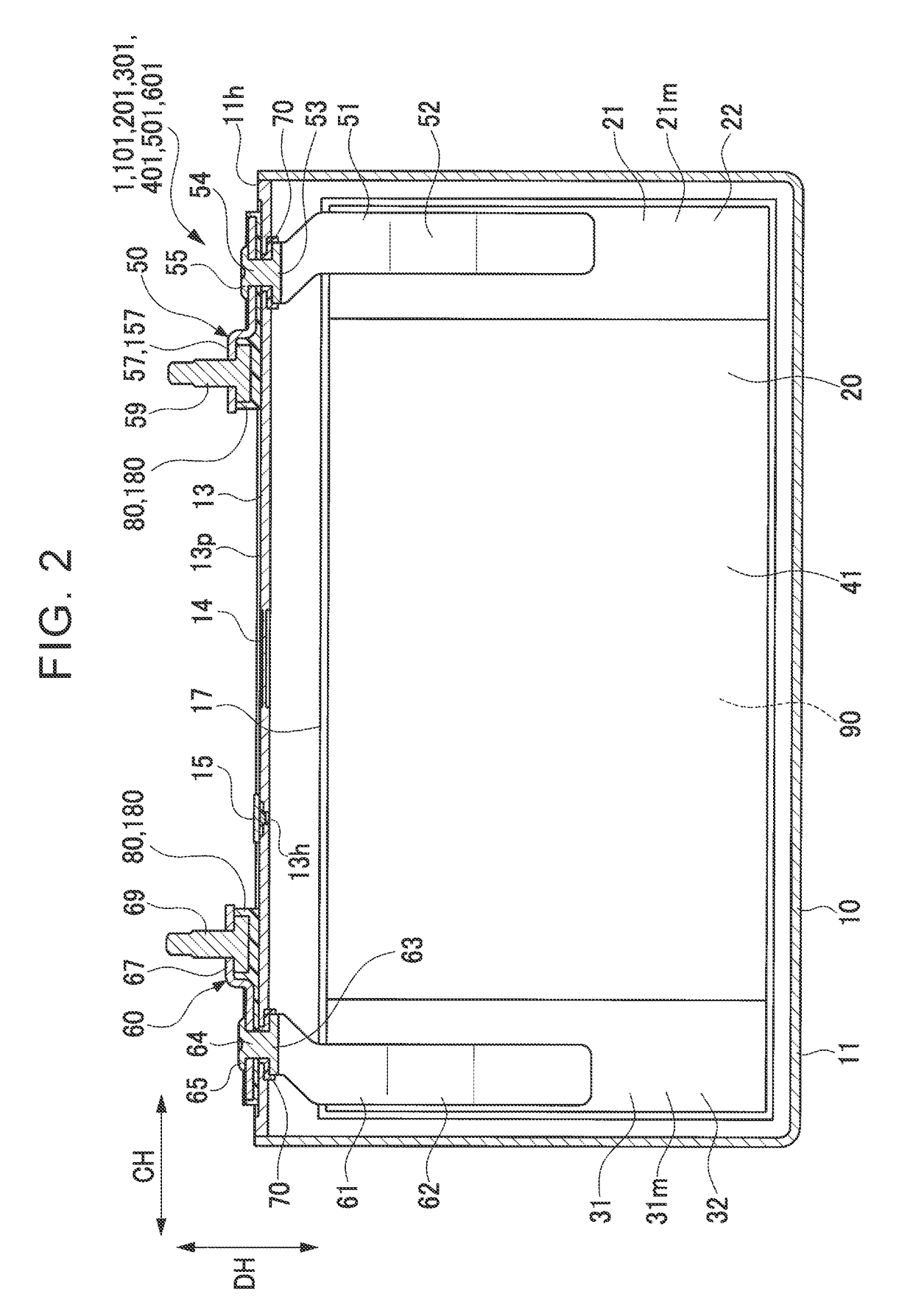
[0041]An embodiment of the disclosure is explained below with reference to the drawings. FIG. 1 and FIG. 2 are a perspective view and a longitudinal sectional view of a lithium-ion secondary battery (which is an example of a battery and is simply referred to as a “battery”) 1, respectively. FIG. 3 is an exploded perspective view of a case lid with terminal members, in which the terminal members 50, 60 are assembled to the case lid member 13. FIG. 4 is a partial sectional view of a structure of the vicinity of a negative electrode terminal member 50 in the battery 1. FIG. 5 is a partial plan view of a structure of the vicinity of the negative electrode terminal member 50 in the battery 1. FIG. 6 is an enlarged partial sectional view of an area where the negative electrode terminal member 50 extends from the battery case. FIG. 7 is a plan view of an external insulating member used in the battery 1. FIG. 8 is an explanatory view of forming of weld beads by using laser beams. In the exp...


PUM


Abstract

A battery includes a battery case, an external metallic member, an external resin member which is present between the battery case and the external metallic member, a heat transfer inhibiting portion configured to restrain heat transfer from the external metallic member to the external resin member, and a current collector member including an extending portion that extends from an inside of the battery case to an outside of the external metallic member, and a rivet portion that expands from the extending portion to a radially outer side and fixes the extending portion, the external metallic member, and the external resin member to the battery case. The rivet portion and the external metallic member include a weld bead that connects the rivet portion and the external metallic member with each other. The heat transfer inhibiting portion is provided on the axially inner side of the weld bead.

Description

INCORPORATION BY REFERENCE[0001]The disclosure of Japanese Patent Application No. 2016-022517 filed on Feb. 9, 2016 including the specification, drawings and abstract is incorporated herein by reference in its entirety.BACKGROUND[0002]1. Technical Field[0003]The disclosure relates to a battery.[0004]2. Description of Related Art[0005]A battery, in which an electrode body is housed in a battery case, is known. In the battery, an extending portion of a current collector member connected with the electrode body inside the battery case is extended outside the battery case, and the extending portion of the current collector member and an external metallic member are fixed to the battery case through an external resin member by making riveting deformation of a rivet portion of the current collector member. The external metallic member is arranged outside the battery case and allows the extending portion to be inserted in its insertion hole (for example, Japanese Patent Application Publica...

Claims


Application Information

Patent Timeline
IPC IPC(8): H01M2/06H01M2/30H01M10/658H01M2/26H01M50/176H01M50/528H01M50/55H01M50/553H01M50/562
CPCH01M2/06H01M10/658H01M2/30H01M2/26H01M10/0525H01M50/528H01M50/553H01M50/176H01M50/562H01M50/55Y02E60/10
Inventor TAKASU, JUNTA
Owner TOYOTA JIDOSHA KK
Learn More