
Lighting device for coupling light from a light source into a light guide plate

a technology of light source and light guide plate, which is applied in the direction of optical light guide, instruments, optics, etc., can solve the problems of degrading or even melting of materials, leds can be sensitive to mechanical loads, and work with high-power leds can have additional problems, etc., to achieve light efficiency, reduce the visibility of light spots, and high light intensity

Inactive Publication Date: 2017-07-27
SIGNIFY HLDG BV
View PDF7 Cites 6 Cited by
  • Summary
  • Abstract
  • Description
  • Claims
  • Application Information

AI Technical Summary

Benefits of technology

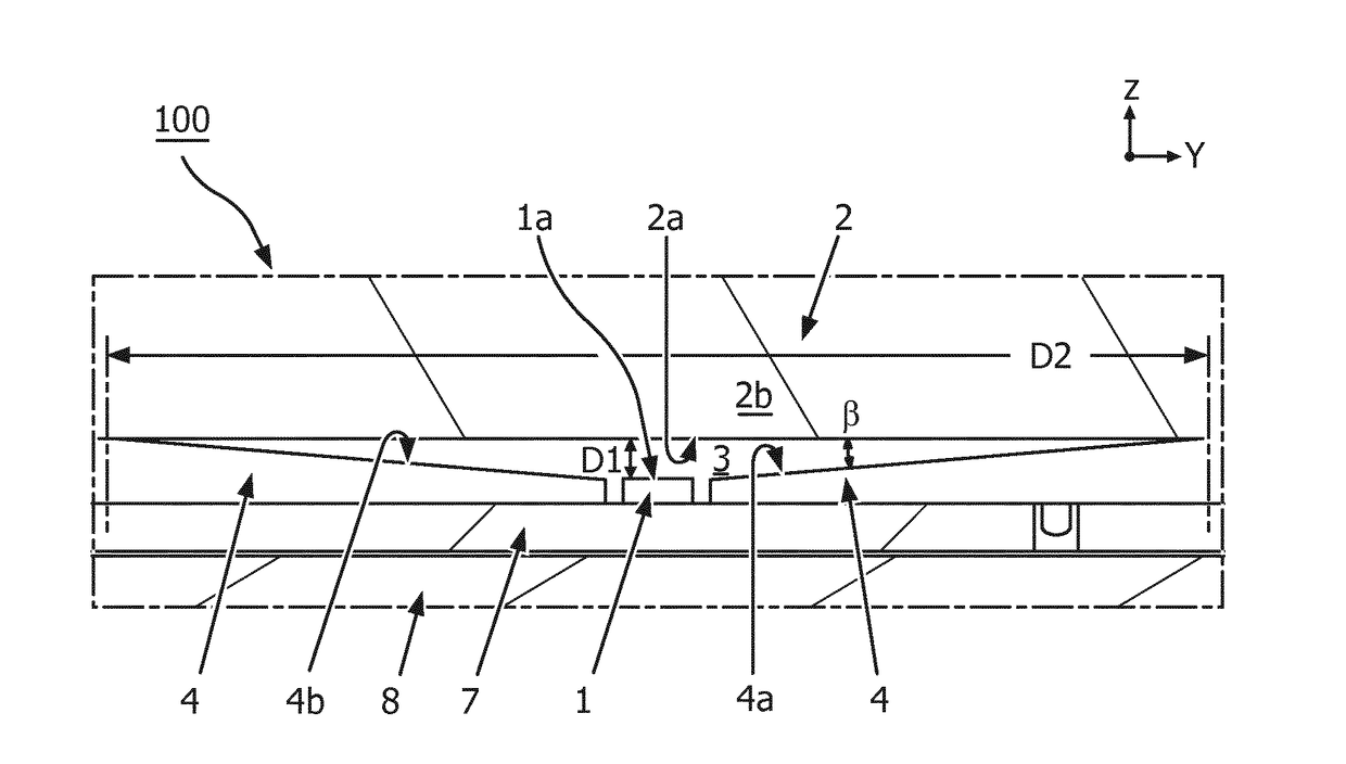
The patent text describes a device that uses a tapered reflection surface to improve the efficiency and spread of light. By using a gas-filled gap between the light source and the light guide plate, the heat and mechanical load problems are alleviated. The tapered surface also redirects light reflected by the light entry surface, increasing the percentage of transmitted light. The device can be used in light therapy devices, where high light intensity is needed. The technical effects of the device include reduced heat transfer, improved light efficiency, and reduced visibility of light spots.

Problems solved by technology

However, working with high power LEDs can have additional problems.
For example, the LEDs may become very hot, thereby degrading or even melting the material (typically plastic, more specifically PMMA) of the light guide plate.
Furthermore, the LEDs can be sensitive to mechanical load.
However, the gap may result in loss of light entering the plate and assembly problems for maintaining the distance between LED and light guide plate within a tolerance range.
However, a drawback of the prior art light devices is that only light at a relatively small angle of incidence is directly projected into the light guide plate, causing loss of light and visible light spots at the entrée of the LED in the plate.
Furthermore, while a curved surface can be useful for reflecting light that directly originates from the light source towards the light entry surface, it is less suited for redirecting light already reflected off the light entry surface.
It is noted that also diffuse reflections may occur, but on average the effect may still cause bending of light towards the normal.
For the radiation part, air does not help.
So, creating gaps will have only limited effect on the direction of the heat flow, although the insulating effect will help.
The main problem with the application of high power LEDs is the high concentration of heat generated in a very small light source resulting in a very high heat flow around the LED, resulting in a very high temperature of the directly surrounding materials.

Method used


Image

  • Lighting device for coupling light from a light source into a light guide plate
  • Lighting device for coupling light from a light source into a light guide plate
  • Lighting device for coupling light from a light source into a light guide plate

Examples


Embodiment Construction

[0032]Unless otherwise defined, all terms (including technical and scientific terms) used herein have the same meaning as commonly understood by one of ordinary skill in the art to which this invention belongs as read in the context of the description and drawings. It will be further understood that terms, such as those defined in commonly used dictionaries, should be interpreted as having a meaning that is consistent with their meaning in the context of the relevant art and will not be interpreted in an idealized or overly formal sense unless expressly so defined herein. In some instances, detailed descriptions of well-known devices may be omitted so as not to obscure the description of the present systems. Terminology used for describing particular embodiments is not intended to be limiting of the invention. As used herein, the singular forms “a”, “an” and “the” are intended to include the plural forms as well, unless the context clearly indicates otherwise. The term “and / or” incl...


PUM


Abstract

The present disclosure concerns a lighting device (100) comprising a light source (1) and a light guide plate (2). The light guide plate (2) is disposed at a distance (D1) from the emitter surface (1a) with an air gap (3) therebetween. A side reflector (4) surrounds the emitter surface (1a) of the light source and bounds the gap (3) between the emitter surface (1a) and the light entry surface (2a). The side reflector (4) comprises a tapered reflection surface (4a) adjacent the emitter surface (1a) and facing the light entry surface (2a). The tapered reflection surface (4a) is disposed at a tapering angle (β) towards the light entry surface (2a). The tapering angle (β) is configured such that any light emitted by the emitter surface (1a) within the opening angle (Φ) of the light source (1) is not reflected by the reflection surface (4a) before being received for the first time by the light entry surface (2a).

Description

TECHNICAL FIELD AND BACKGROUND[0001]The present disclosure relates to a lighting device such as a light therapy device.[0002]Light therapy consists of the exposure of a subject to a prescribed dosage of light. For example, light having a particular frequency may be used to treat circadian rhythm disorders. In the last decades, several types of light therapy devices have entered the market which typically comprise CFL lamps or LED lights. To improve eye comfort and freedom of design, these light sources can be combined with light guide plate technology. A light guide plate comprises a light entry surface at one or more edges of the light guide plate. The light entry surface is configured to receive incident light from the light source and transmit said light to an interior of the light guide plate. The interior is configured to guide and distribute the light over a (front) surface of the plate, e.g. via internal reflection and / or by reflective surfaces at the sides of the plate, exce...

Claims


Application Information

Patent Timeline
Patent Type & Authority Applications(United States)
IPC IPC(8): F21V8/00A61N5/06
CPCG02B6/0031G02B6/0083G02B6/0085A61N2005/0665A61N2005/0663A61N2005/0651A61N5/06A61N2005/0664G02B6/0091A61N2005/0642
Inventor BRADA, YPE BERNARDUS
Owner SIGNIFY HLDG BV
Learn More