Pulse power device based on annular ceramic solid state line

a technology of annular ceramic and solid state line, which is applied in the direction of high-tension/heavy-dress switches, air-break switches, electrical apparatus, etc., can solve the problem of requiring an extra long electrical length, unable to meet the actual requirements, and the power-volume ratio of these devices remains a gap between the actual requirements and the power-volume ratio of the device, so as to improve the quality of waveform, reduce the effect of reflection

Inactive Publication Date: 2017-07-06
INST OF APPLIED ELECTRONICS CHINA ACAD OF ENG PHYSICS
View PDF0 Cites 7 Cited by
  • Summary
  • Abstract
  • Description
  • Claims
  • Application Information

AI Technical Summary

Benefits of technology

The present invention solves technical problems such as waveform degradation and large field intensity by using an annular ceramic solid-state pulse forming line that is fully enclosed and silver coated, eliminating reflection and point discharge. Gas switches are directly welded onto the pulse forming lines and arranged co-axially to reduce circuit inductance, improve pulse efficiency, and optimize waveform quality. The co-axial construction also reduces system size and improves power-volume ratio by 50%. The pulse forming lines generate a high voltage pulse with a fast pulse front edge.

Problems solved by technology

Although some miniaturized pulse power sources have been developed based on the methods mentioned above, a gap remains between the power-volume ratios of these devices and the actual requirements.
Moreover, as the volumes of the existing high-voltage ceramic capacities or the film capacities get larger, it needs multi stage capacitor and inductor to produce better flat-top pulse voltage, which leads to bigger and bigger volume of the whole pulse network.
With regard to method 2 mentioned above, when the pulse is generated by using the high voltage transmission lines, as the dielectric constant is relatively low (at present, the well-known deionized water has the highest dielectric constant, i.e. 81), the step of generating a high voltage pulse having a certain width requires an extra long electrical length, and this method is not good for miniaturizing a pulse power device.
With regard to the method 3 mentioned above, a higher dielectric constant can be obtained by using the line-type plate solid line, however, as the line-type plate solid line generates the pulse based on the reflection principle thereof, the quality of the waveform is degraded due to the reflection in the transmission; as the existing pulse devices are connected to the switch by lead wires, a higher loop-inductor which is not good for forming a high-voltage pulse at the front edge of a fast pulse would be generated; meanwhile, in this case, the structural design would be complicated as multi-stages Marx are superimposed.
Although it improves the compact and miniaturized design of the solid-state pulse forming line comparing with the line-type plate solid-state pulse line, the filed intensity of the tips of the silvering layer at the two ends of an opening will be increased than other areas and it results in a technical problem of point discharge.
Meanwhile, the increased filed intensity might lead a breakdown of the ceramic material and a surface flashover.
Regarding to the pulse power devices used to generate high voltage provided in existing techniques, one technical issue to be solved is how to provide a miniaturize pulse power device, for generating a high voltage pulse output having a fast front edge, a compact type, a better wave-form and high power-volume ratio.
At the same time, as the adder of the multiple-stage solid-state pulse forming lines is accomplished, the affect on the ambient electrical field of each forming line is weak, the problems such as the distortion of electrical fields are not easily generated.

Method used


Image

  • Pulse power device based on annular ceramic solid state line
  • Pulse power device based on annular ceramic solid state line
  • Pulse power device based on annular ceramic solid state line

Examples


Embodiment Construction

[0039]Except for the mutually exclusive technical features and / or the mutually exclusive steps, all of the technical features, the methods or steps provided in the present disclosure can be combined in any form.

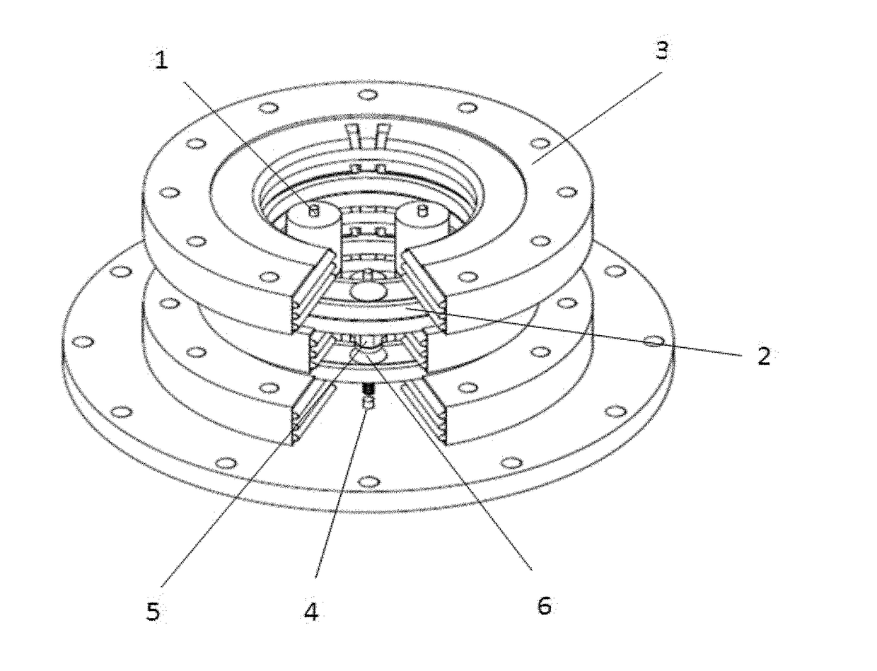
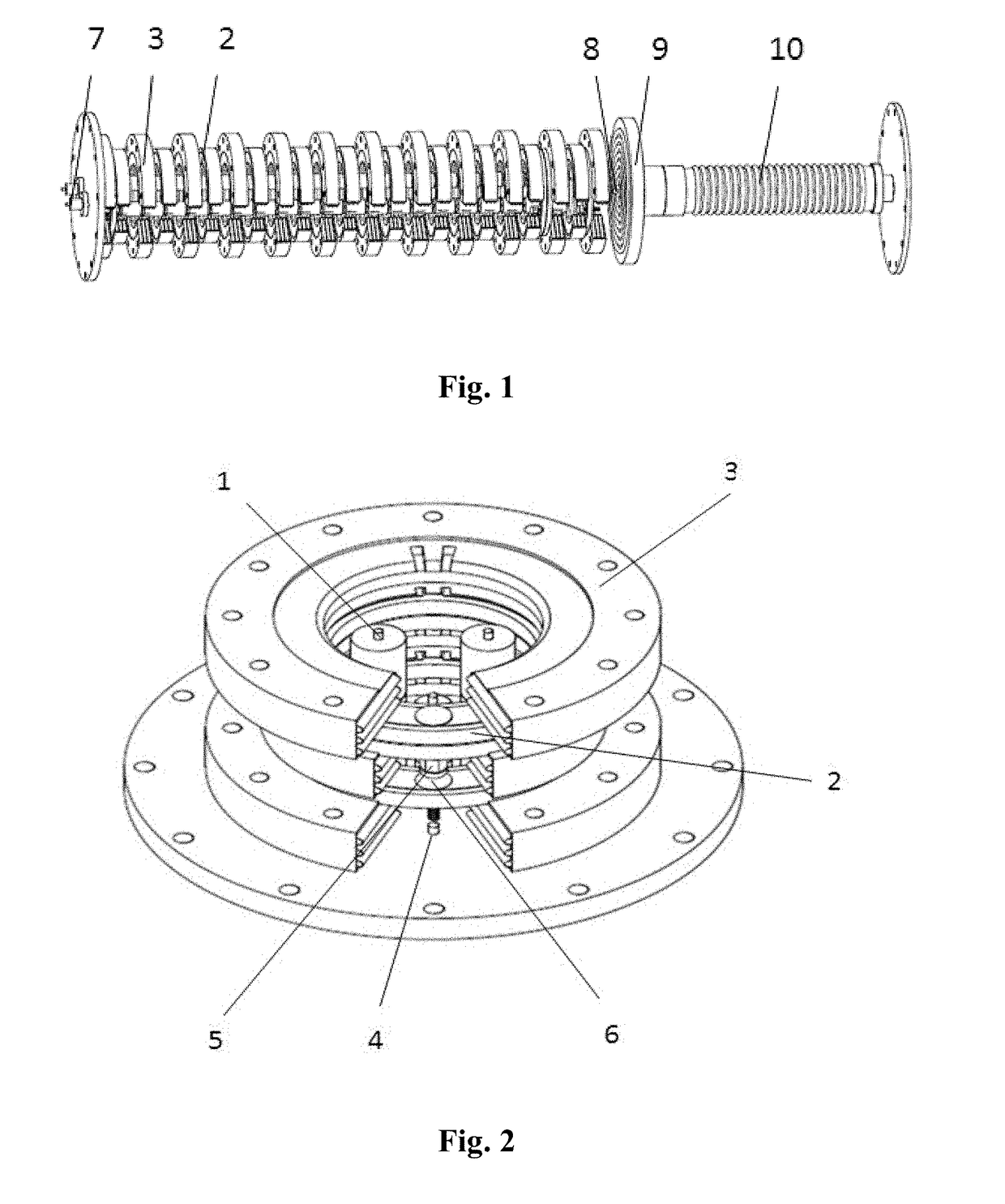
[0040]As illustrated by FIG. 1, according to the present disclosure, a pulse power device based on annular ceramic solid lines includes a pulse generating section provided in a cylinder and a load section provided in a cylinder as well, wherein the two sections are separated from each other hermetically by an insulating plate 9 between the two sections. The insulation of pulse generating section is implemented by inflating SF6 (or the mixture of SF6 and N2), the insulation of the load section is implemented by introducing transformer oil, and the two insulating mediums are separated from each other by an organic glass insulating plate interposed therebetween. Here, an outer cylinder of the device is not illustrated. The pulse generating section is taken as the main body of th...


PUM


Abstract

A pulse power device based on an annular ceramic solid state line. The pulse power device comprises several pulse forming lines (2), two charging inductors (1), and several gas switches that are connected as a whole based on Marx voltage superposition. The pulse forming lines (2) are annular pulse forming lines (2), and the annular surface of each annular pulse forming line (2) is provided with one gas switch. The annular pulse forming lines (2) are successively superposed together to form a column structure through the gas switches. Each charging inductor (1) passes through the inner ring of each annular pulse forming line (2) to be disposed inside the column structure. An annular insulation plate (3) is disposed between every two annular pulse forming lines (2).

Description

BACKGROUND[0001]Technical Field[0002]The invention relates to power pulse, and more particularly, to a rectangle pulse high voltage generating device. The invention can be applied in the fields related to photoflash photography, high-power microwave, high-power frequency radio, materials research and so on.[0003]Related Art[0004]Currently, miniaturizing a high-power pulse power source becomes a major trend in the technical development. As the electron beam used in the researches related to HPM, X-ray, laser and other aspects have higher requirements, there is a serious need for developing compact pulse power sources. Therefore, researches of rectangle pulse power sources related to voltage adders based on Marx become a hot research topic both at home and abroad. Recently, several methods have been developed for implementing an output for the voltage adder by using the Marx technique, these methods include: 1. generating a pulse by PFN (Pulse Forming Network); 2. generating a pulse b...

Claims


Application Information

Patent Timeline
Patent Type & Authority Applications(United States)
IPC IPC(8): H03K3/53H01H33/64
CPCH01H33/64H03K3/53H03K5/04
Inventor TAN, JIELUO, MINWANG, PENGKANG, QIANGXIANG, FEILUO, GUANGYAOYANG, XIAOLIANG
Owner INST OF APPLIED ELECTRONICS CHINA ACAD OF ENG PHYSICS
Why Eureka
Try Eureka