
Two-channel point-diffraction interferometer

a point-diffraction interferometer and two-channel technology, applied in the direction of instruments, measurement devices, structural/machine measurement, etc., can solve the problem of not being able to achieve the same best focus, and achieve the effect of low vibration sensitivity of the whole device and stability

Active Publication Date: 2017-07-06
DIFROTEC OU
View PDF3 Cites 6 Cited by
  • Summary
  • Abstract
  • Description
  • Claims
  • Application Information

AI Technical Summary

Benefits of technology

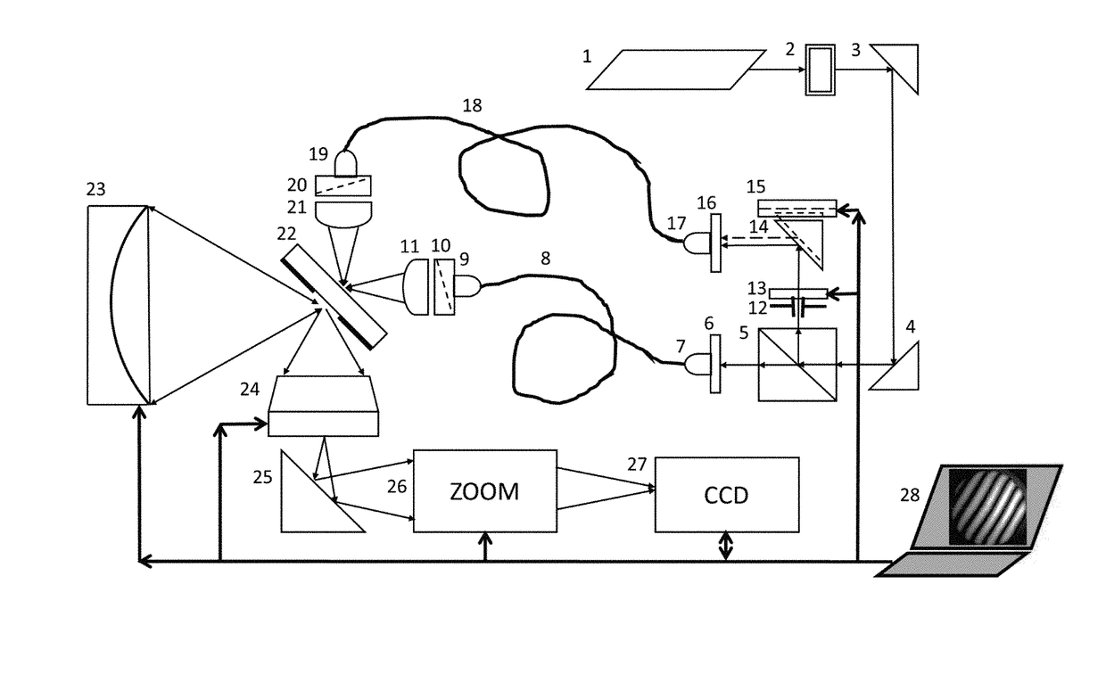
The present invention proposes an improved interferometer that allows the light of two channels to be focused independently to pinholes on a plate with pinholes due to flexibility of single-mode optical fibers, thereby improving stability and reducing vibration sensitivity of the whole device. The focusing lines of the channels are performed strictly along x, y, z directions, which helps achieve the highest possible signal-to-noise ratio during testing glass or plastic uncoated mirrors. The short optical paths of the two channels also help achieve the same best focus in any orientation of the interferometer. By using a pinhole plate with two pinholes, mutual influence of the diffracted fields of the two channels can be reduced, resulting in better accuracy and image quality.

Problems solved by technology

In the patented scheme it is principally impossible to attain the same best focus as in the new scheme.

Method used


Image

  • Two-channel point-diffraction interferometer
  • Two-channel point-diffraction interferometer
  • Two-channel point-diffraction interferometer

Examples


Embodiment Construction

[0014]A two-channel point-diffraction interferometer consists of the following details and elements:

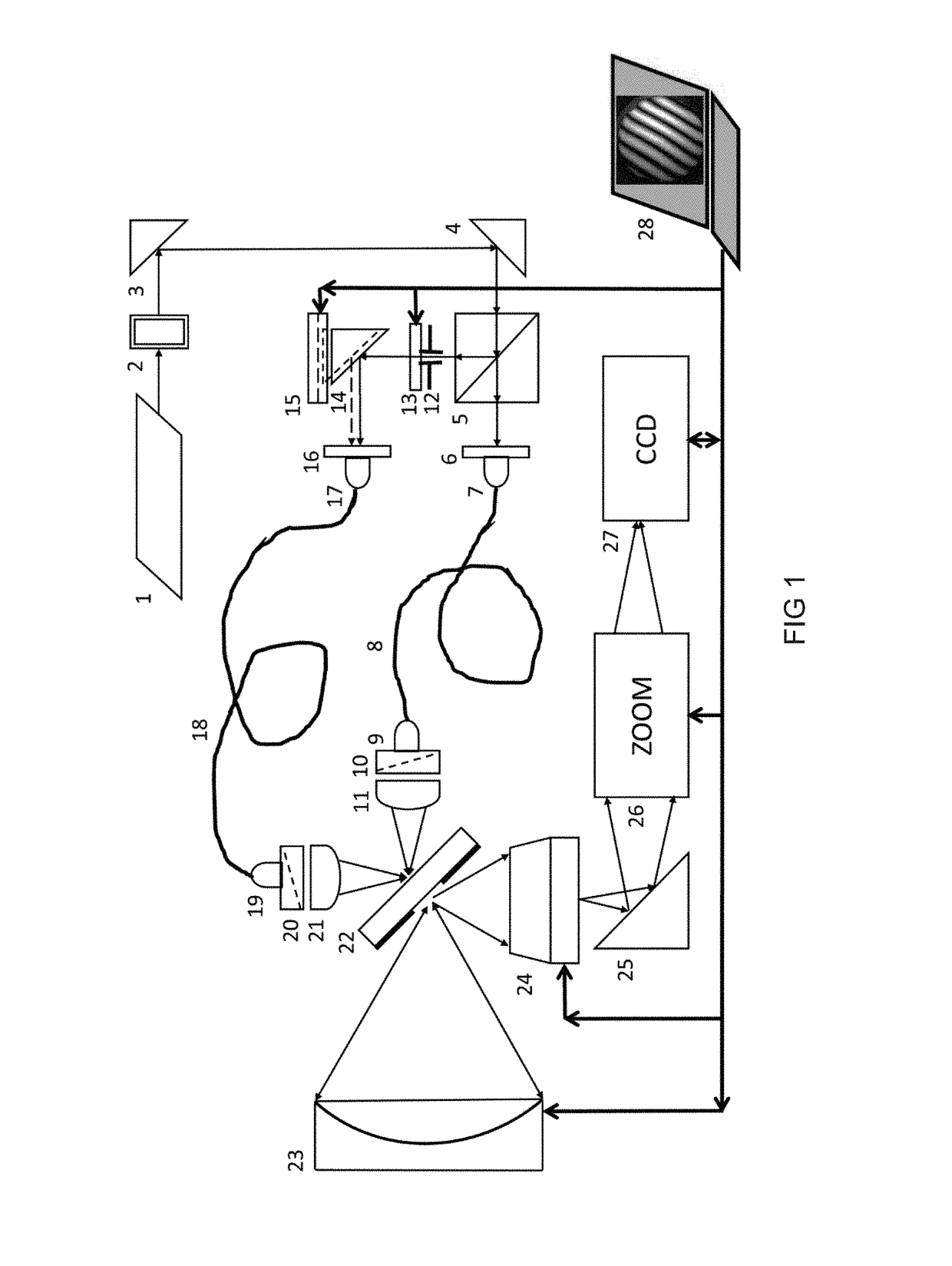
[0015]A frame and housing, a laser source (1), a Faraday isolator (2), a right angle prism (3), a right angle prism (4), a beam splitter (5), an unit for adjusting two angles θx, θy (6), a collimator (7), a single-mode optical fibre keeping polarization of light unchanged (8), a working collimator (9), a plate (λ / 4) (10), an working channel objective (11), an attenuating stop (12), a first piezo shifter (13), a right angle prism (14), a second piezo shifter (15), an unit for adjusting two angles θx, θy (16), a second collimator (17), a single-mode optical fibre keeping polarization of light unchanged (18), a reference collimator (19), a plate (λ / 4) (20), an reference channel objective (21), a plate with pinholes (22), a test part (23), an imaging objective (24), a right angle prism (25), a ZOOM system (26), a CCD camera (27), and a computer (28) (see FIG. 1 and FIG. 4 and FIG. 5).

[001...


PUM


Abstract

The present invention is related with the two-channel point-diffraction interferometer for testing the optical systems or optical elements. The two-channel point-diffraction interferometer comprising a laser source inducing a linearly polarized laser beam which is divided by a beam splitter to a working channel and to a reference channel whereas the one half of light as working channel is directed from the first collimator to the working collimator by a first single-mode optical fibre to keep polarization of light unchanged, and another half of light as reference channel is directed from the second collimator to the reference collimator by a second single-mode optical fibre to keep polarization of light unchanged.

Description

PRIORITY[0001]This application claims priority of European Patent Application number EP15203223.1 which was filed on Dec. 30, 2015 and the contents of which are incorporated herein by reference.TECHNICAL FIELD[0002]The present invention concerns the area of optical instrument making and can be used for testing optical systems and samples, including those having a high level of accuracy of correction of aberrations and errors, with deformations of wave front less than 1 / 90 wavelength, in particular the present invention is related with the two-channel point-diffraction interferometer for testing the optical systems or optical elements / samples.BACKGROUND ART[0003]The document KR 20050102264 A (KOREA ELECTRO TECH RES INST) 26.10.2005 describes the interferometer intended for testing optical surfaces and optical systems. The interferometer comprises: laser; elements of an objective of the illuminating system; inclined flat mirror, in whose reflection coating there is a pinhole aperture,...

Claims


Application Information

Patent Timeline
IPC IPC(8): G01B9/02
CPCG01B9/02038G01B2290/70G01B9/02035G01B9/02097G01B9/02027G01M11/0271G01B11/2441
Inventor VOZNESENSKIY, NIKOLAYVOZNESENSKAIA, MARIIAVOZNESENSKAIA, TATIANA
Owner DIFROTEC OU
Learn More