
Size-Adjustable Online Wheel Deburring Device

a wheel deburring and size adjustment technology, applied in the direction of grinding drives, grinding machine components, manufacturing tools, etc., can solve the problems of no deburring equipment and the deburring effect barely meets use, and achieves the effects of high degree of automation, stable performance, and simple structur

Active Publication Date: 2017-06-29
CITIC DICASTAL
View PDF16 Cites 20 Cited by
  • Summary
  • Abstract
  • Description
  • Claims
  • Application Information

AI Technical Summary

Benefits of technology

The present invention is a device for deburring wheels that can automatically adjust the size of brushes based on the size of the wheels. This allows for mixed-line automatic online deburring and focused processing on the corners of flange roots and rim roots. The device is highly automated, uses advanced technology, has a simple structure, and is safe and stable in performance.

Problems solved by technology

At present, for almost all wheel production enterprises, a large-disc brush is used for carrying out deburring on a back cavity of a wheel on special equipment, this mode has a still permissible effect on wheels with simple front shapes, however, for a majority of wheels, the deburring effect hardly meets use requirements; and almost all wheel production enterprises adopt mixed-line production, i.e., the wheels of different sizes will wait for deburring on a physical distribution roller way simultaneously, at present, no deburring equipment, which can meet online deburring requirements of the wheels of various sizes and meanwhile be used for carrying out targeted processing on burrs formed at flange and spoke corners according to formation modes and distribution characteristics of wheel burrs, is present yet, and to rapidly remove the burrs at the flange and spoke corners in transverse and longitudinal directions is very necessary.

Method used


Image

  • Size-Adjustable Online Wheel Deburring Device
  • Size-Adjustable Online Wheel Deburring Device
  • Size-Adjustable Online Wheel Deburring Device

Examples


Embodiment Construction

[0016]In the following, the details and working conditions of a specific device provided by the present invention are described in combination with the figures.

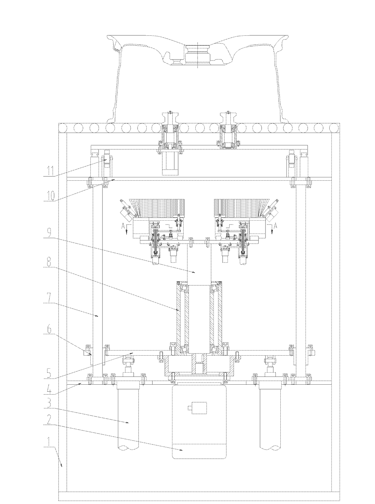
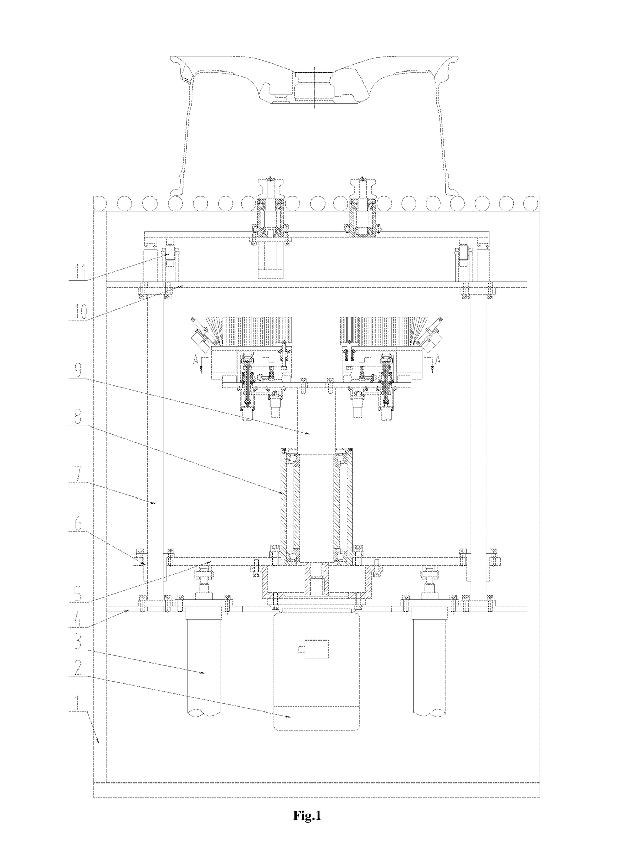
[0017]A size-adjustable online wheel deburring device comprises a synchronous clamping and rotating system, a brush adjustment system and a machine frame 1.

[0018]The synchronous clamping and rotating system comprises a drive motor I 2, lifting cylinders 3, a bottom plate 4, a rising and falling plate 5, guide sleeves 6, guide posts 7, a large bearing block 8, a driving shaft 9, a top plate 10, gears I 11, synchronous gear racks 16, synchronous guide rails 17, a left sliding plate 18, minor bearing blocks 19, synchronous shafts 20, V-type rollers 21, a right sliding plate 22, a clamping cylinder 23 and a drive motor II 24. Four guide posts 7 are fixed between the bottom plate 4 and the top plate 10, and four guide sleeves 6 matched with the guide posts 7 are mounted on the rising and falling plate 5. The drive motor I 2 is mou...


PUM


Abstract

The present invention relates to a size-adjustable online wheel deburring device, which comprises a synchronous clamping and rotating system and two brush adjustment systems which are in bilateral symmetry. When in use, the synchronous clamping and rotating system enables a wheel to rotate in a clamped state, and the diameter of the wheel is detected; driving cylinders enable spline shafts to rise so as to enable jacking blocks to be matched with gears II, and servo motors drive the gears II to rotate through synchronizing belts I; a left brush and a right brush are separately adjusted to appropriate positions through a left gear rack and a right gear rack; the driving cylinders enable the spline shafts to fall so as to enable the jacking blocks to be separated from the gears II; the servo motors drive flange brushes to rotate through the synchronizing belts I and synchronizing belts II; belt pulleys IV guarantee that the synchronizing belts II are always in a tensioned state after the left brush and the right brush are adjusted to the appropriate positions; oblique motors drive oblique brushes to rotate; and a drive motor I enables the brush adjustment systems which are in bilateral symmetry to rotate through a driving shaft, two lifting cylinders lift the wheel through guide posts, and the aim of deburring can be achieved when each brush is in contact with a back cavity of the wheel.

Description

[0001]This application claims priority from CN 201511006534.6, filed on Dec. 29, 2015, the entire content of which is incorporated herein by reference.TECHNICAL FIELD[0002]The present invention relates to a wheel deburring device, and in particular to a size-adjustable online wheel deburring device.BACKGROUND ART[0003]At present, for almost all wheel production enterprises, a large-disc brush is used for carrying out deburring on a back cavity of a wheel on special equipment, this mode has a still permissible effect on wheels with simple front shapes, however, for a majority of wheels, the deburring effect hardly meets use requirements; and almost all wheel production enterprises adopt mixed-line production, i.e., the wheels of different sizes will wait for deburring on a physical distribution roller way simultaneously, at present, no deburring equipment, which can meet online deburring requirements of the wheels of various sizes and meanwhile be used for carrying out targeted proce...

Claims


Application Information

Patent Timeline
Patent Type & Authority Applications(United States)
IPC IPC(8): B24B9/04B24B29/04B24B29/00
CPCB24B9/04B24B29/04B24B29/005B24B27/0076B24B41/02B24B41/06B24B47/00B24B47/12B24B5/44B24B41/067B24B5/01B24B5/12
Inventor XUE, BOWENGUO, JIANDONG
Owner CITIC DICASTAL
Learn More